I’ve wanted to build a small form factor PC (SFFPC) for quite some time. One of my favourite technology YouTube channels is Optimum Tech, and the host specializes in building small ITX form factor PC builds. At this point, building a SFFPC is not super niche, and there’s a sizeable community surrounding it.
The Case
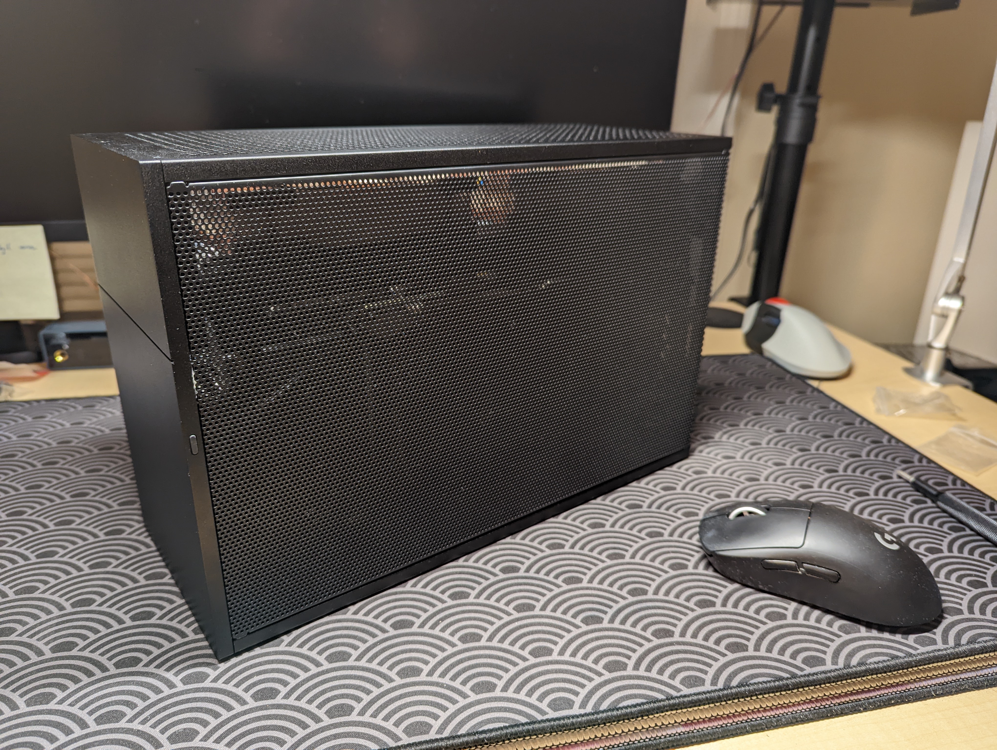
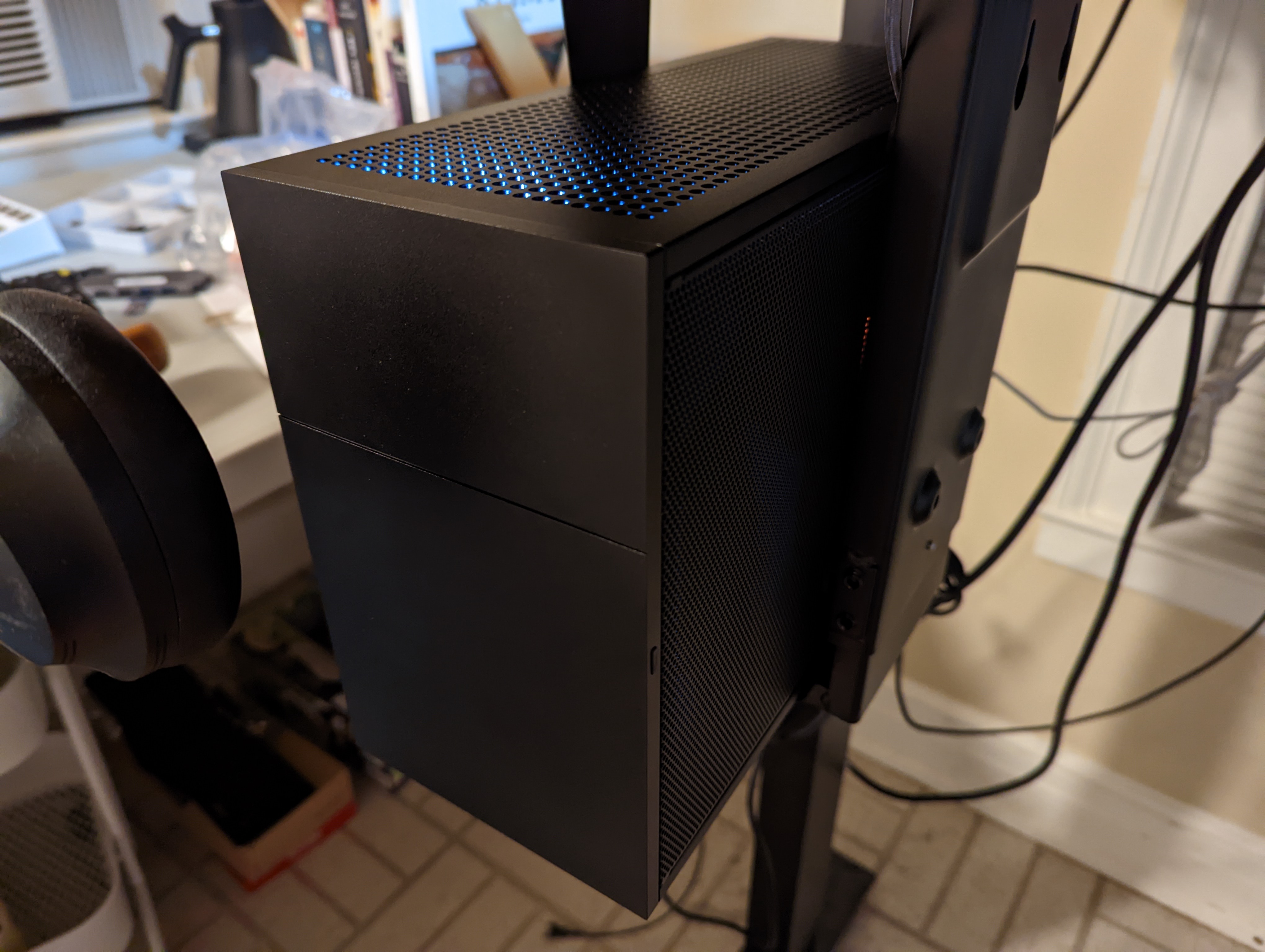
SFFPC builds revolve around the PC case, because that’s what limits the size, and to some extent, the power1 of the build. SFFPC expert, Optimum Tech, has a really high opinion of the FormD T1.
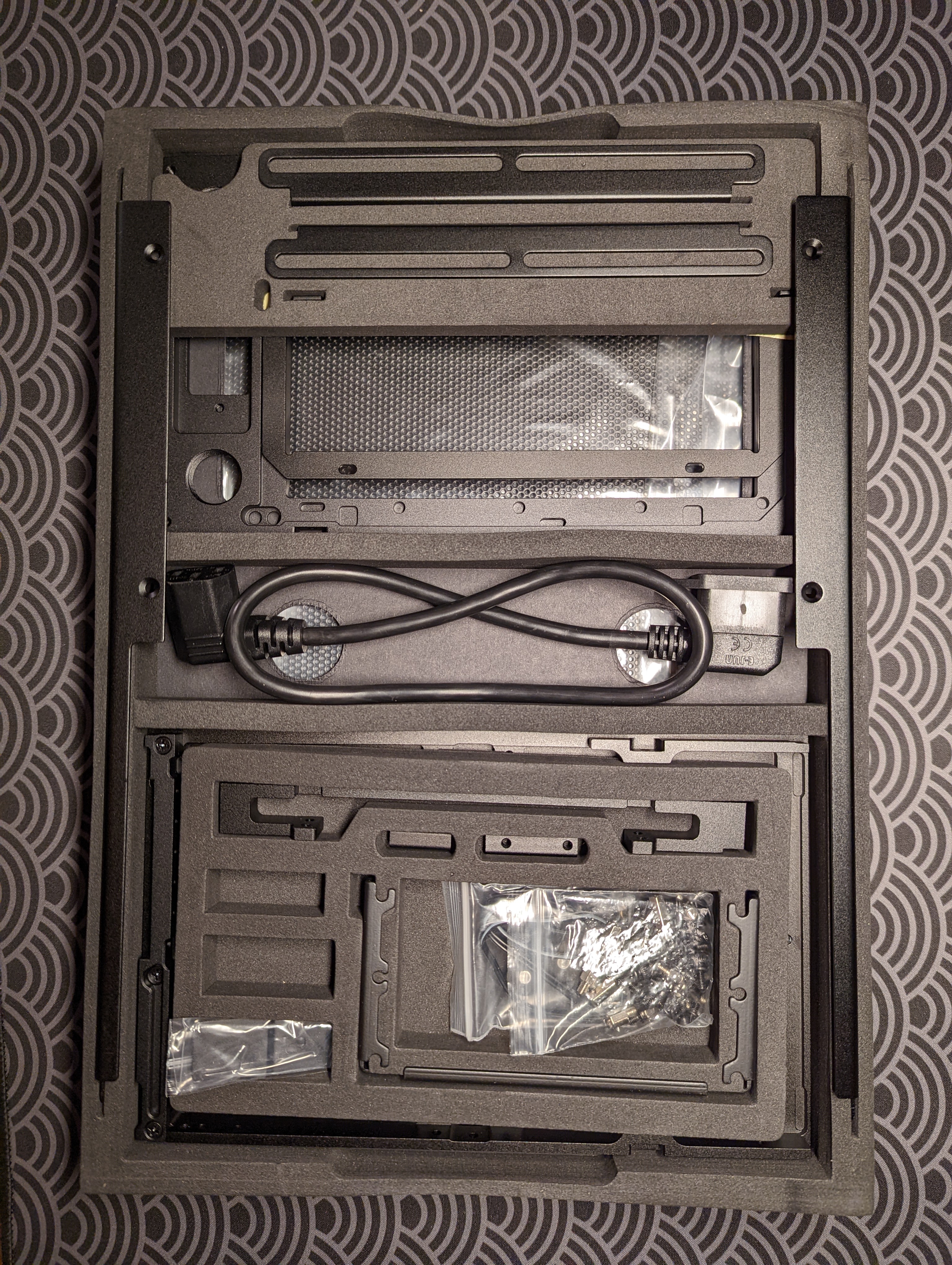
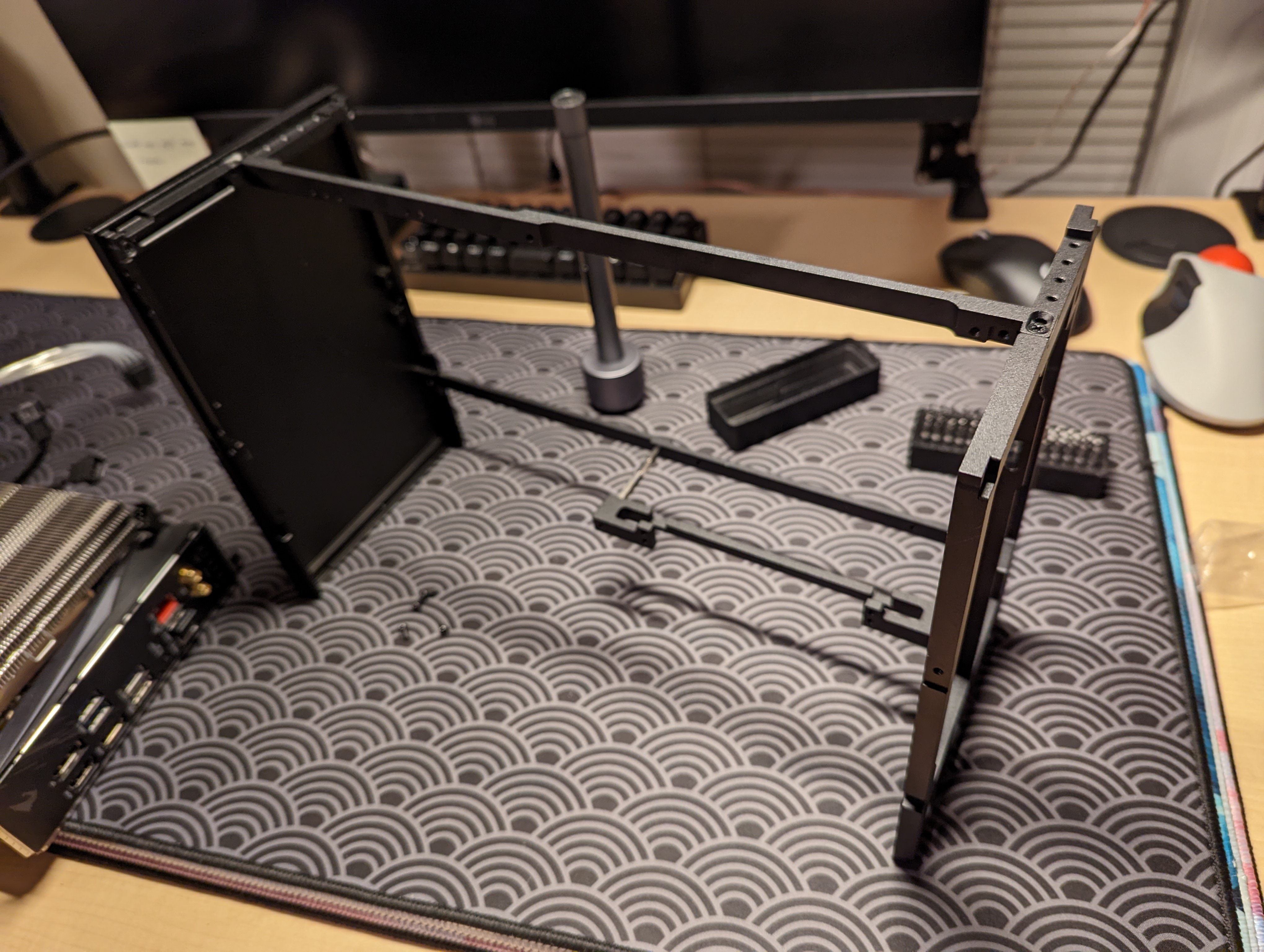
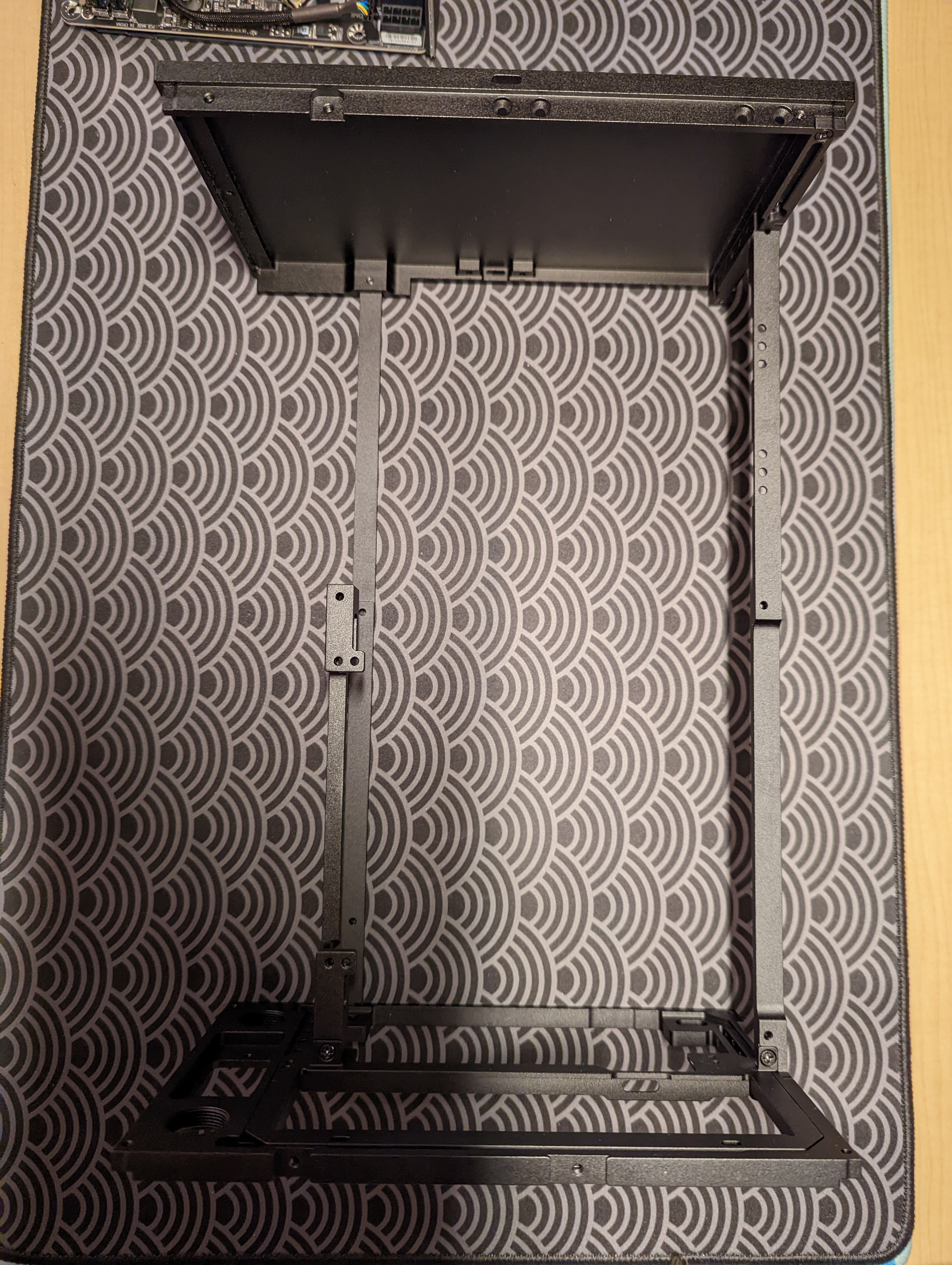
The FormD T1 comes in three possible layouts: the reference layout, the tower layout, and the sandwich layout. Optimum Tech argues that the sandwich layout provides the best cooling performance, and so I purchased a FormD T1-SW case in all black. It arrived flat-packed after a few weeks, and I used the online manual to assemble it together. Assembly was surprisingly straightforward and clear, thanks to the manual.
Testing the Power Supply
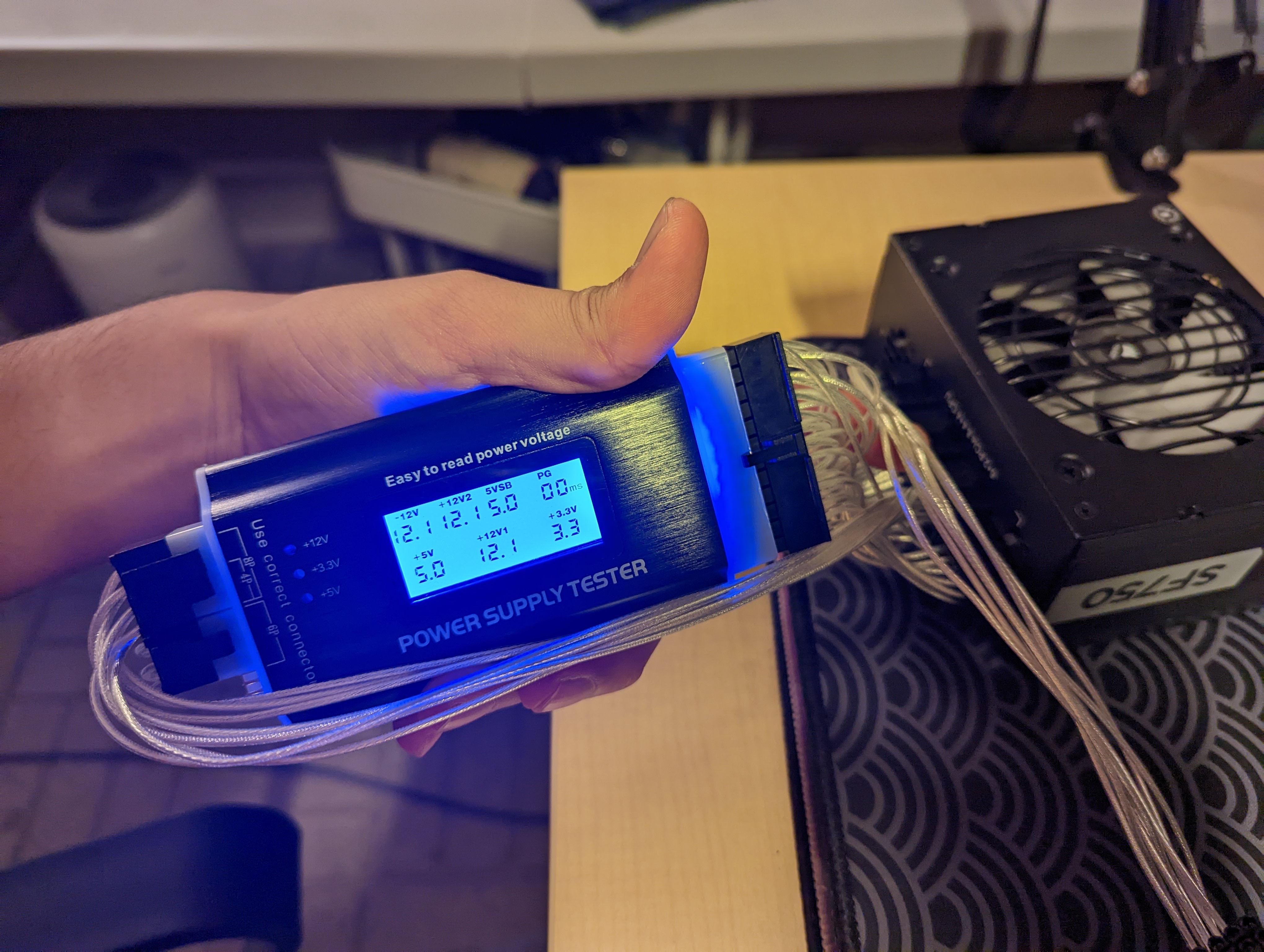
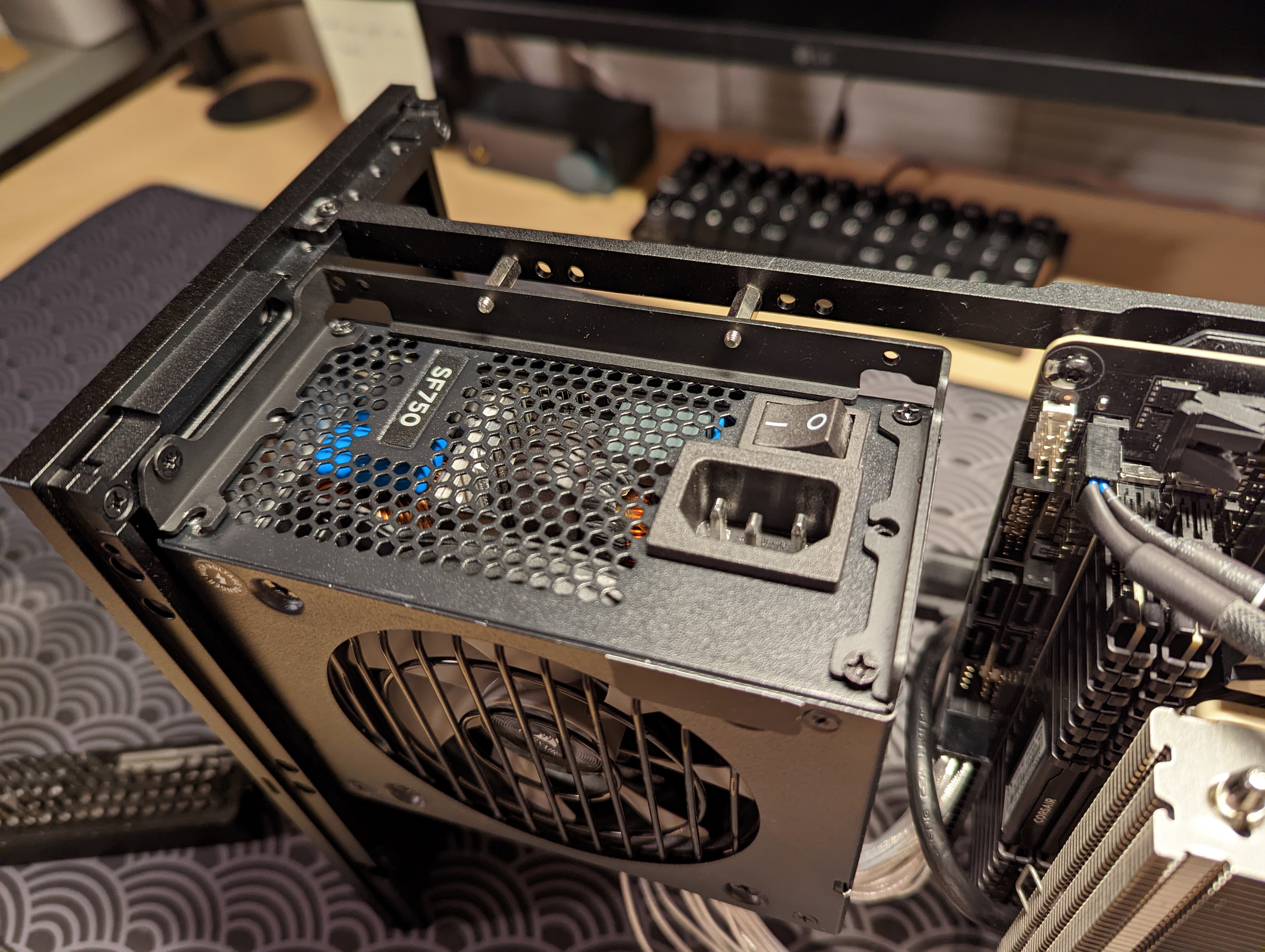
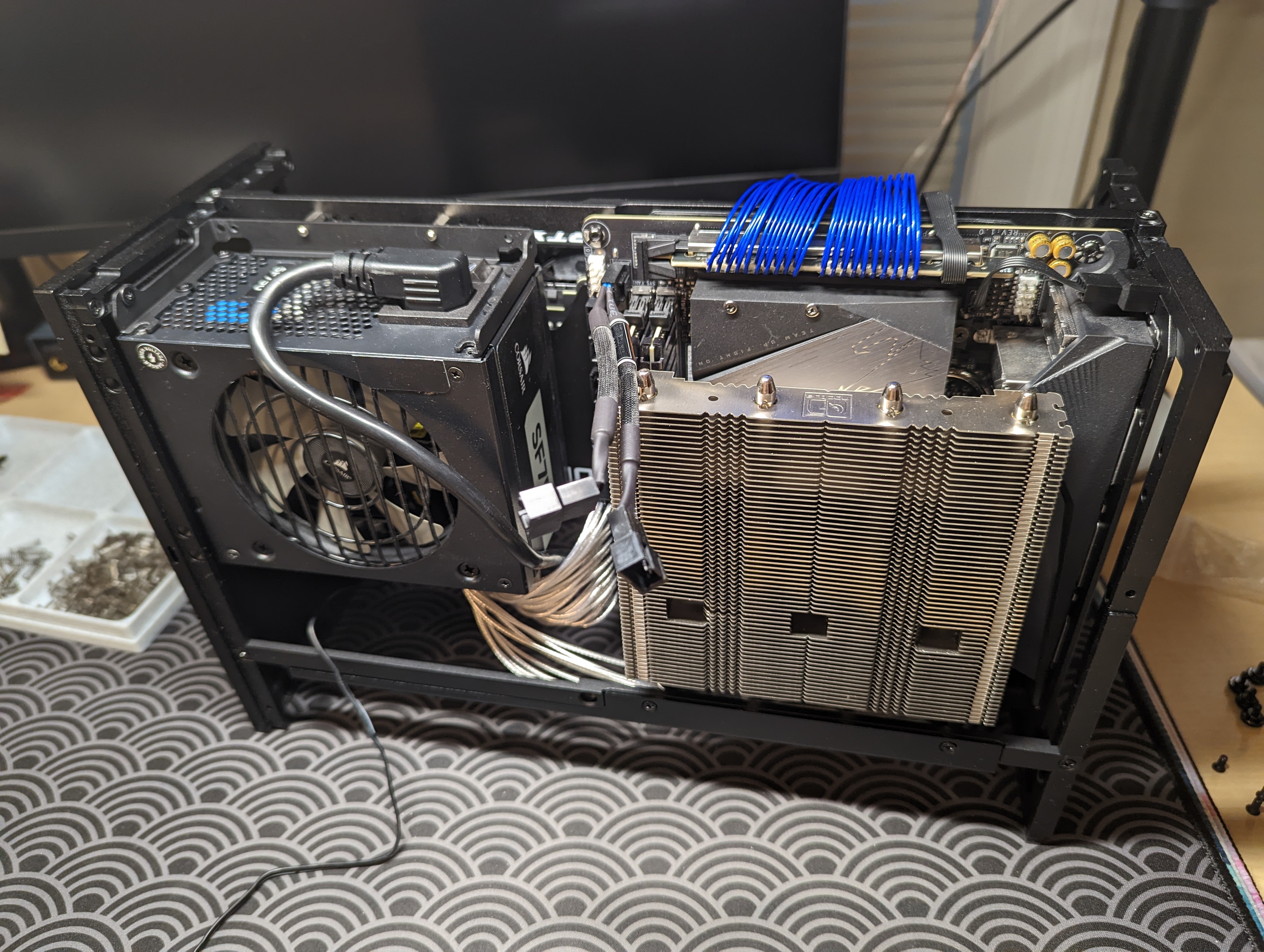
I’m using a Corsair SF750 power supply, which is probably the most popular ITX form factor PSU. Before assembling all my parts together, I tested the integrity of the PSU with a PSU tester, for my peace of mind. I connected the various pins from the PSU to the PSU tester, and checked that the voltage readings were all correct.
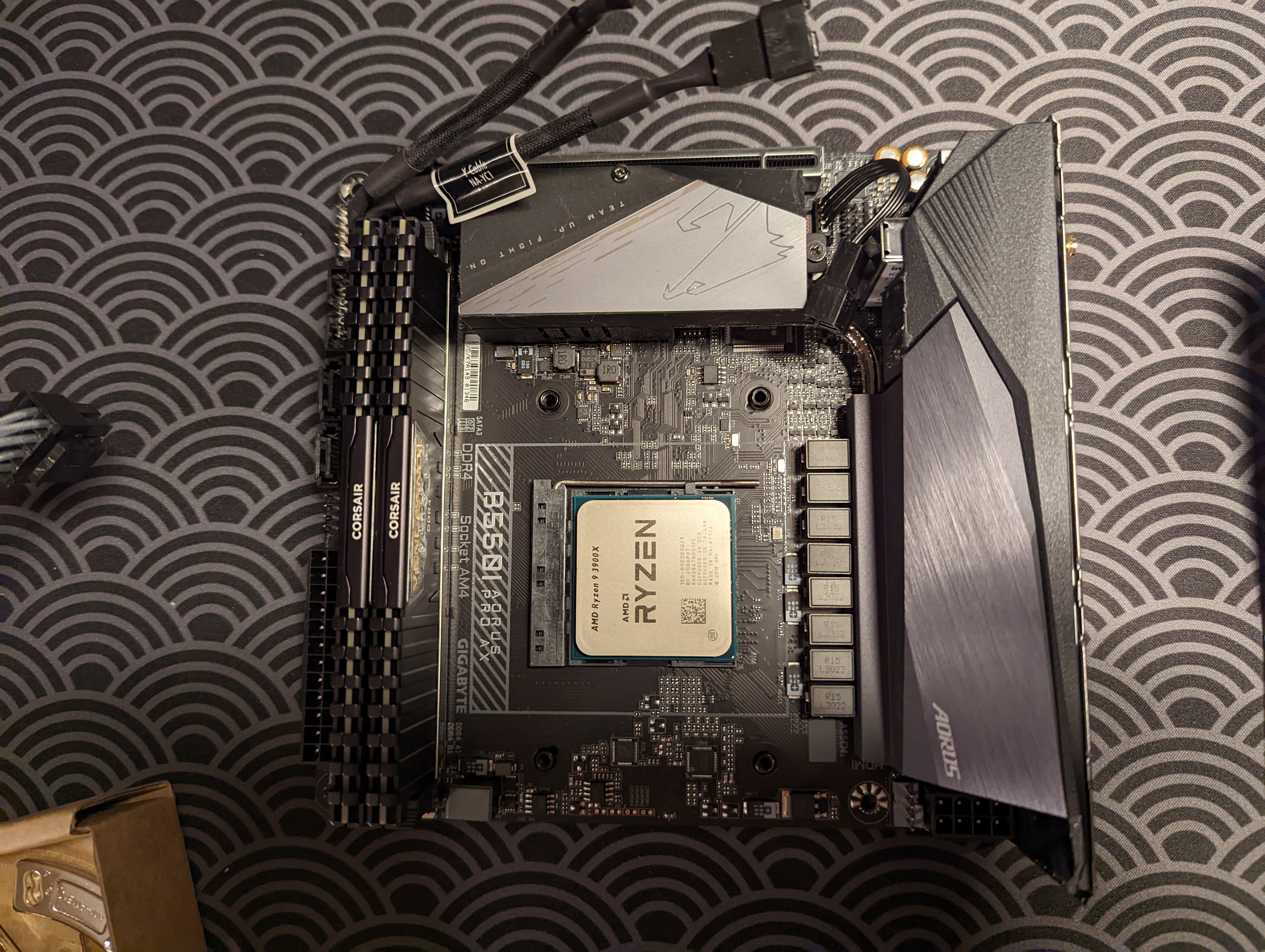
Assembling the Motherboard
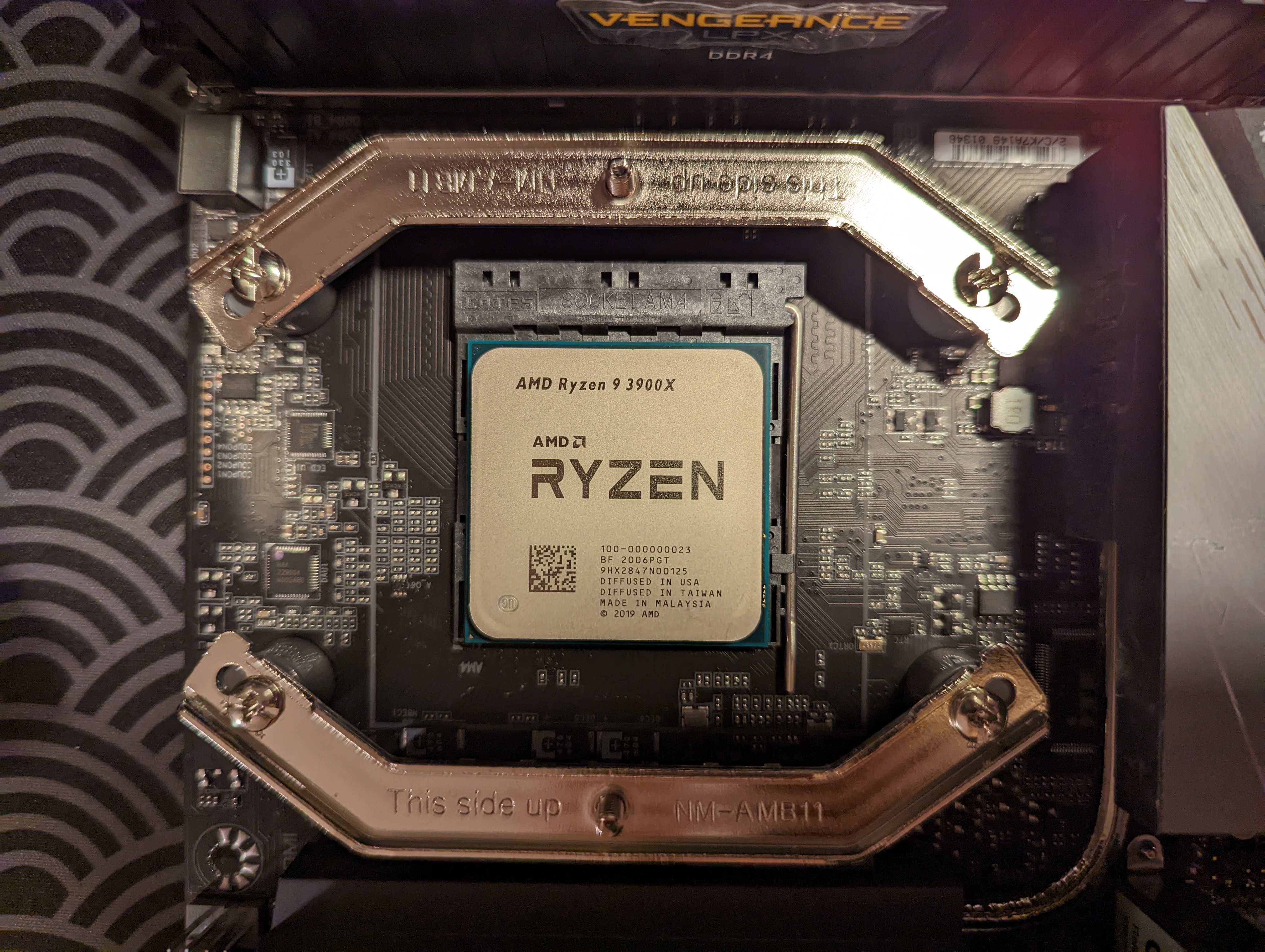
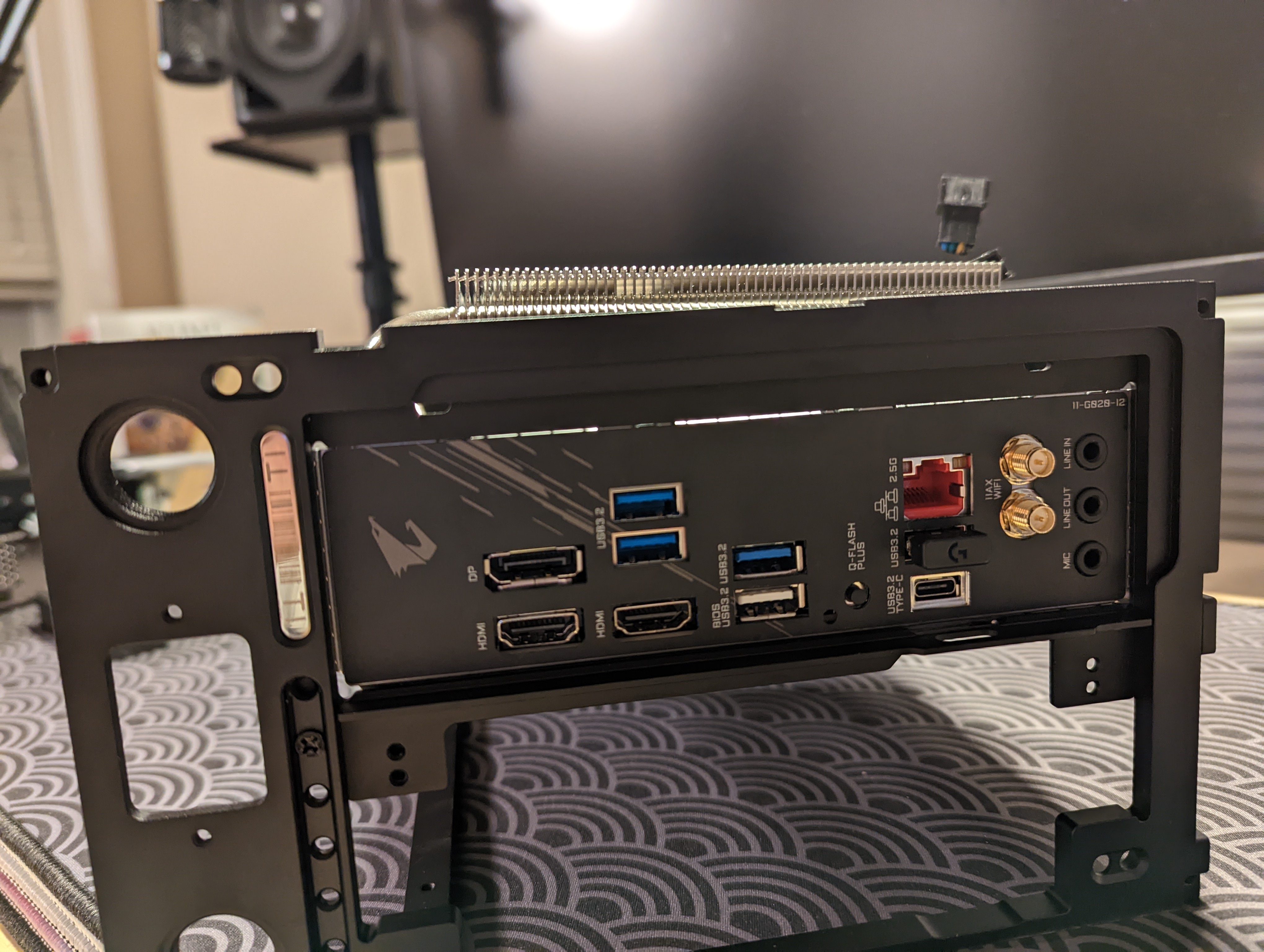
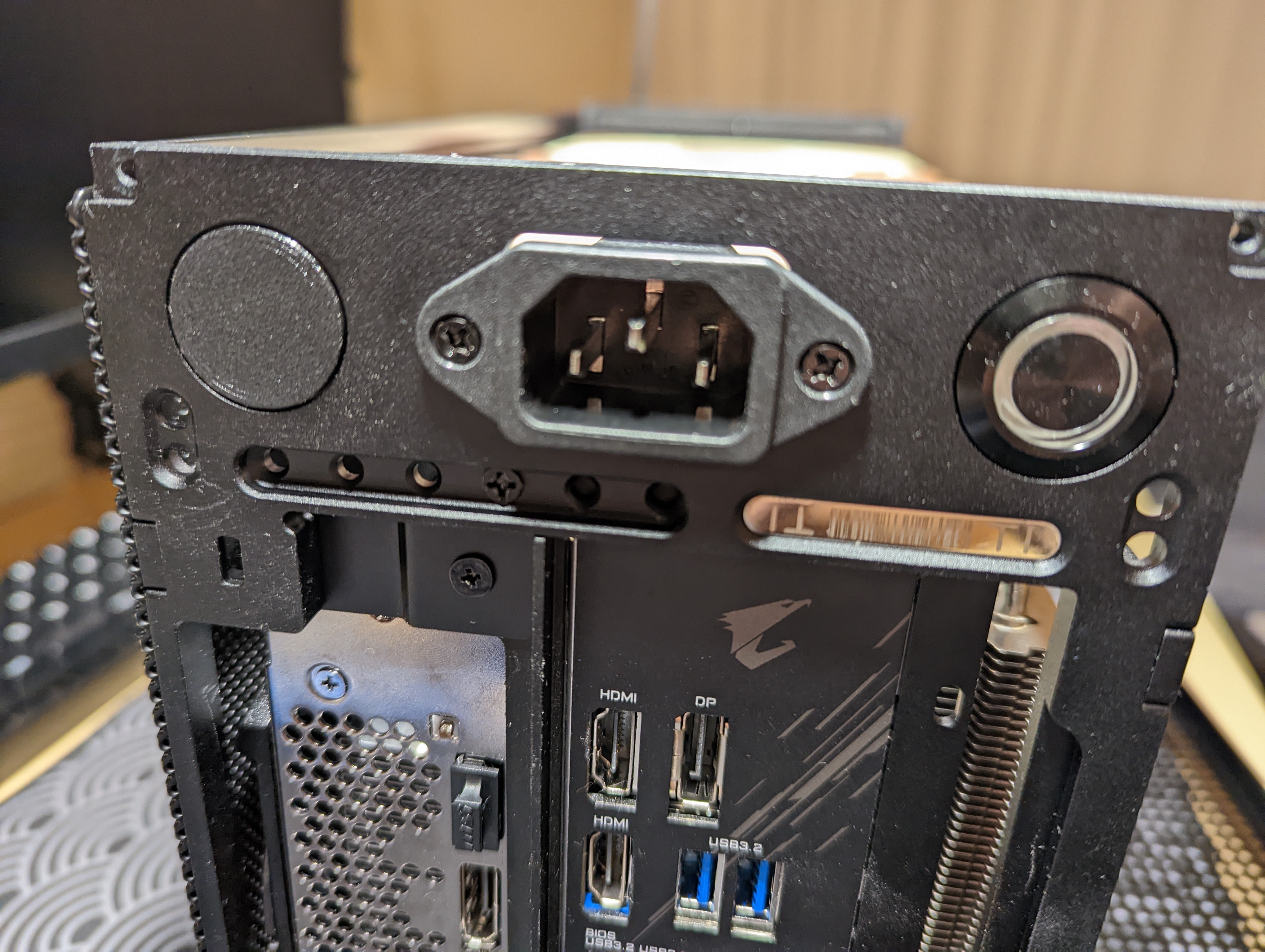
I’m using an AMD Ryzen 9 3900X as my CPU with a Gigabyte B550I Aorus Pro AX motherboard.
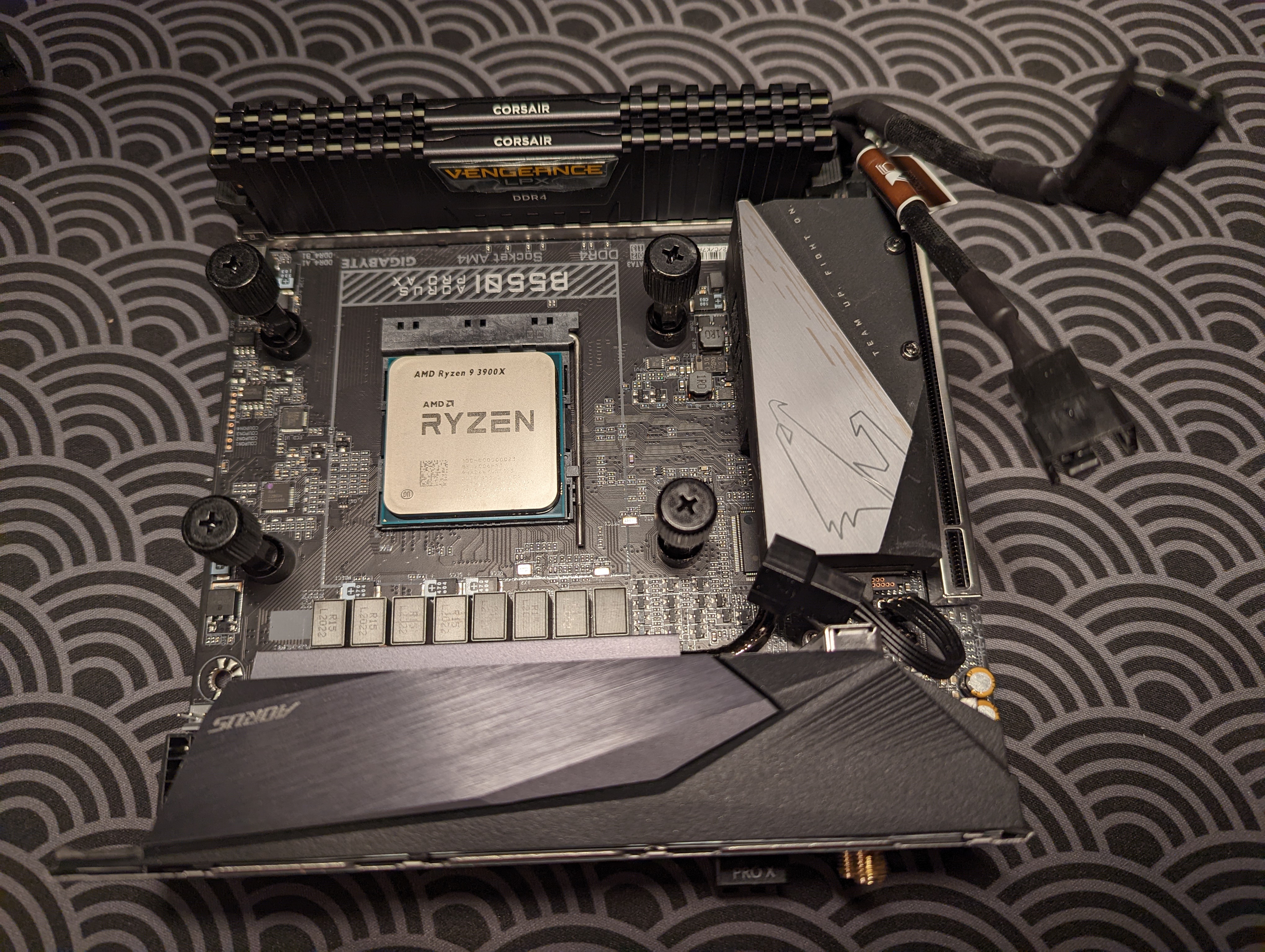
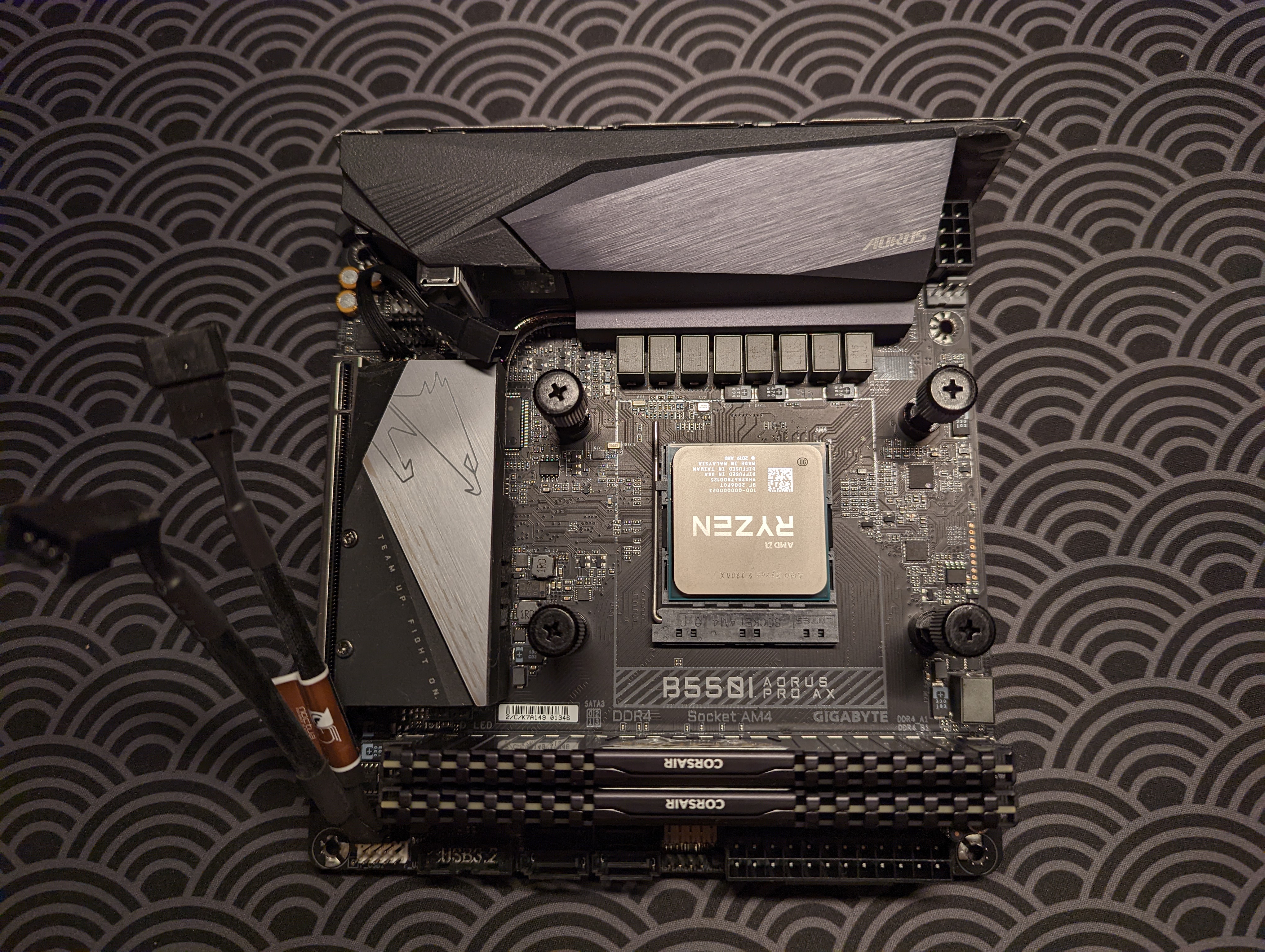
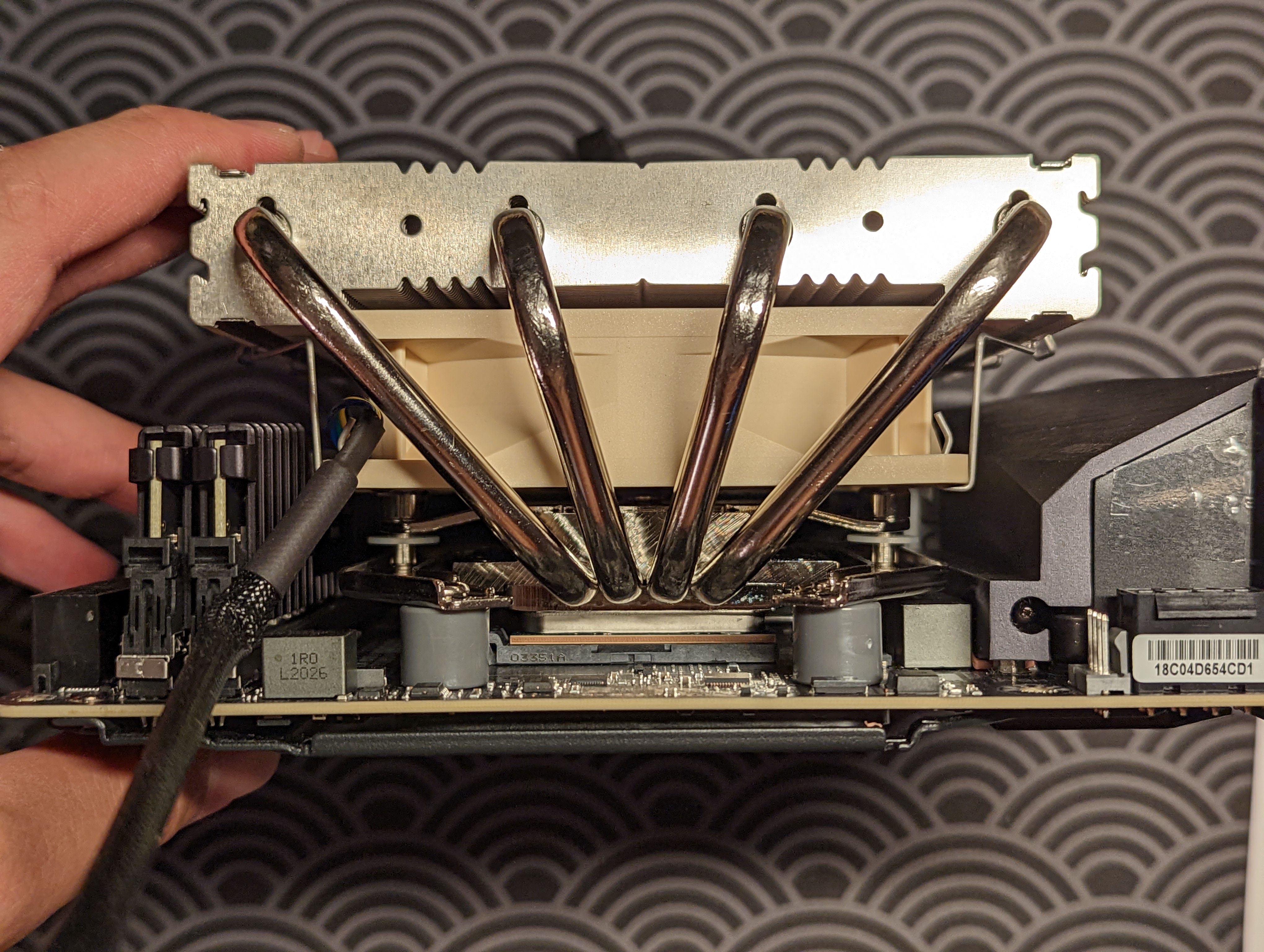
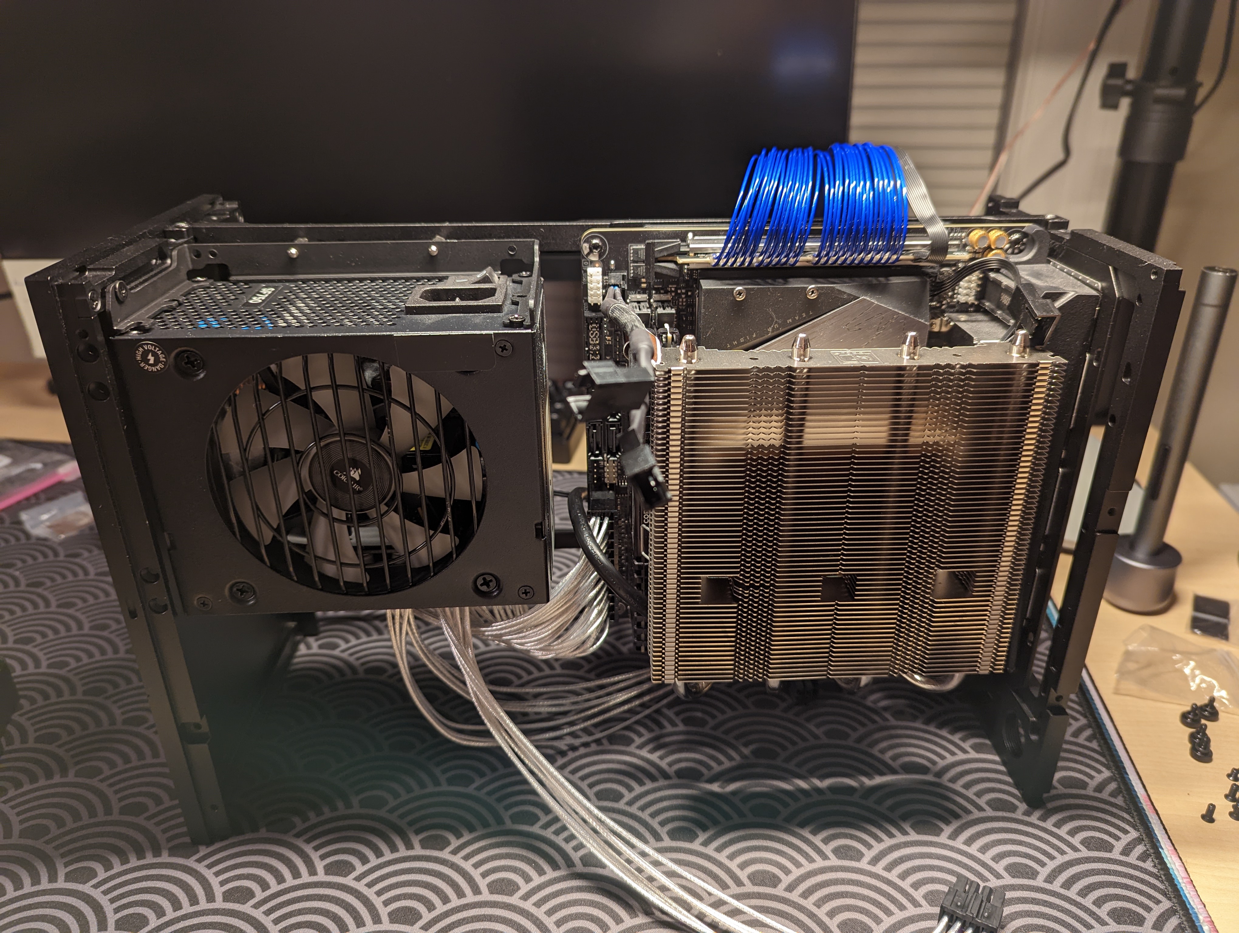
For the CPU cooler, I’m opting for a Noctua NH-L12 (Ghost S1 Edition) air cooler. Installing the cooler on my AMD motherboard requires that I screw in AM4 brackets and spacers.
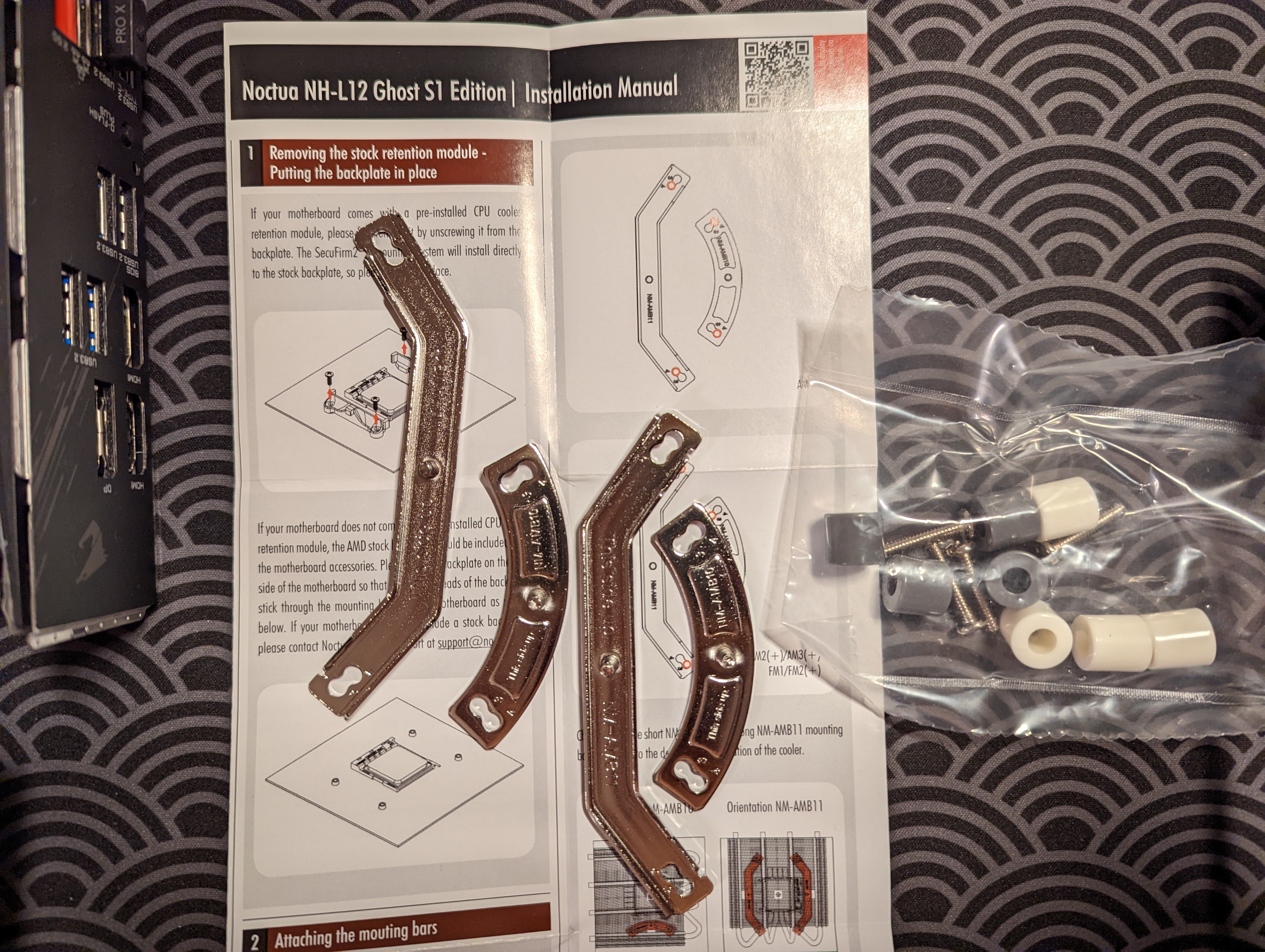
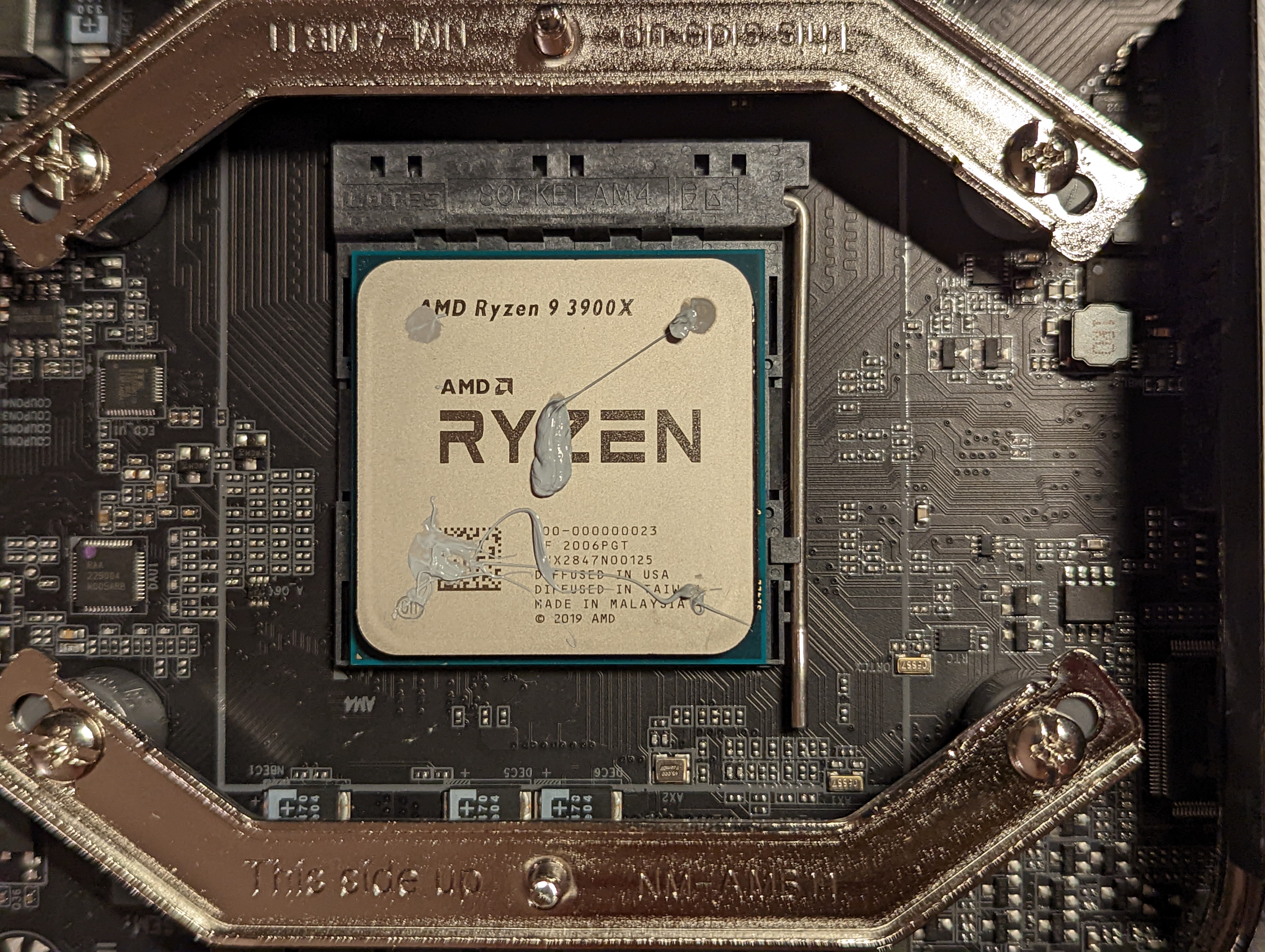
I apply some CPU cooler—not too much though, because everyone on the internet likes to go on and on about how if you apply too much cooling paste, the cooling efficiency decreases. I then screw the CPU cooler in place above the CPU using a long screwdriver.
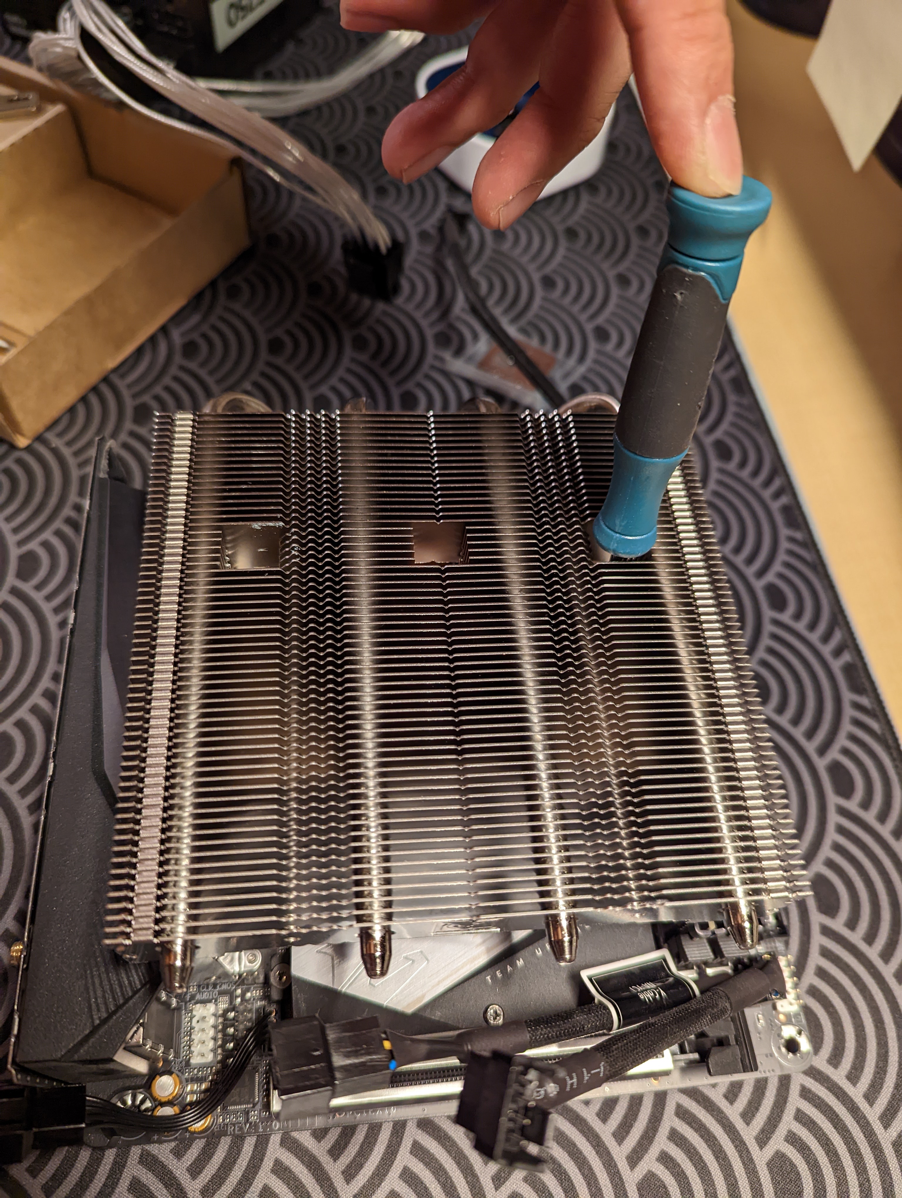
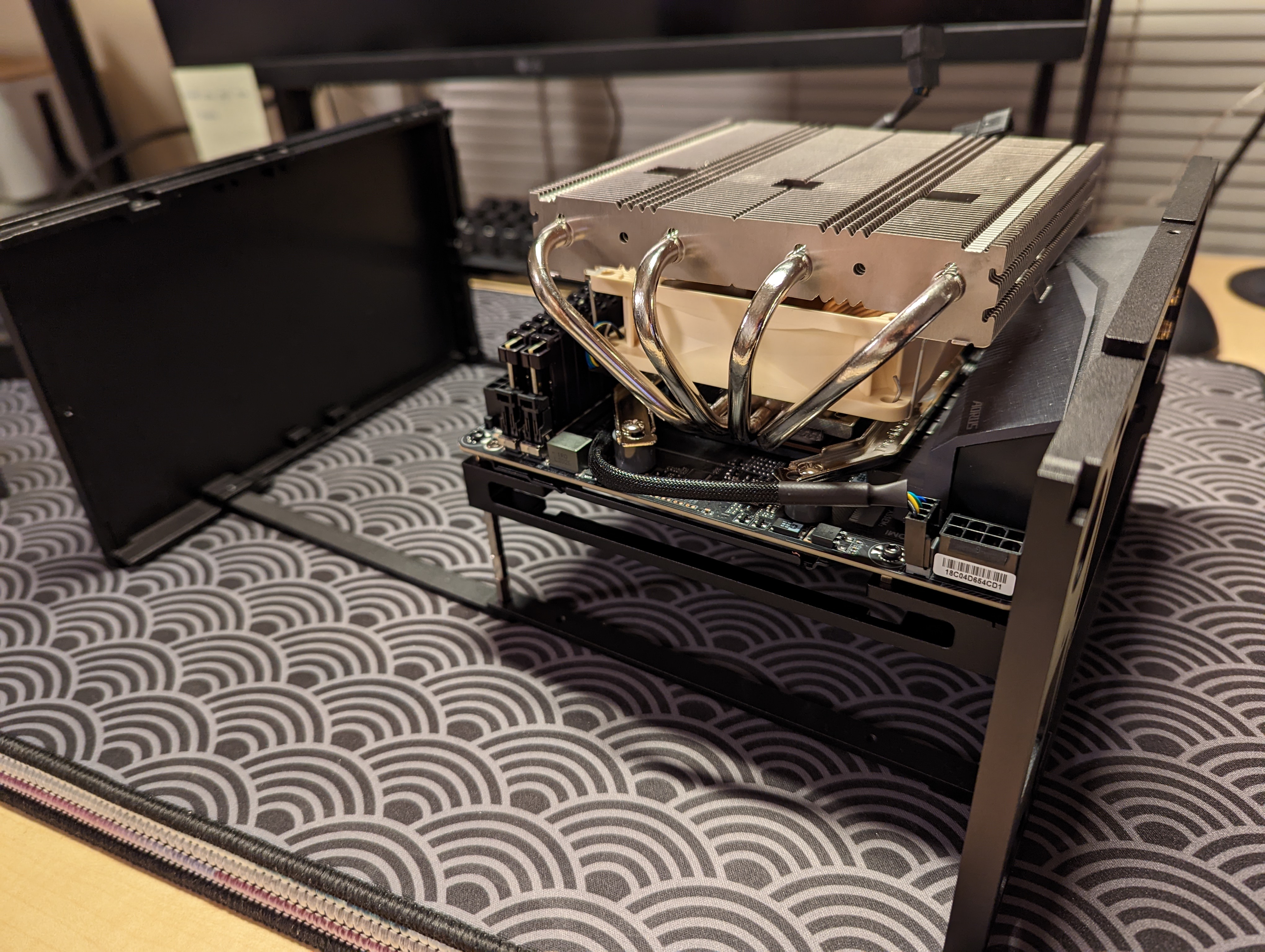
We then place the motherboard into the case.
Installing the Power Supply
Next, we install the power supply unit. The FormD T1 comes with a bracket for mounting the PSU. I use some screws to mount the PSU onto the bracket.
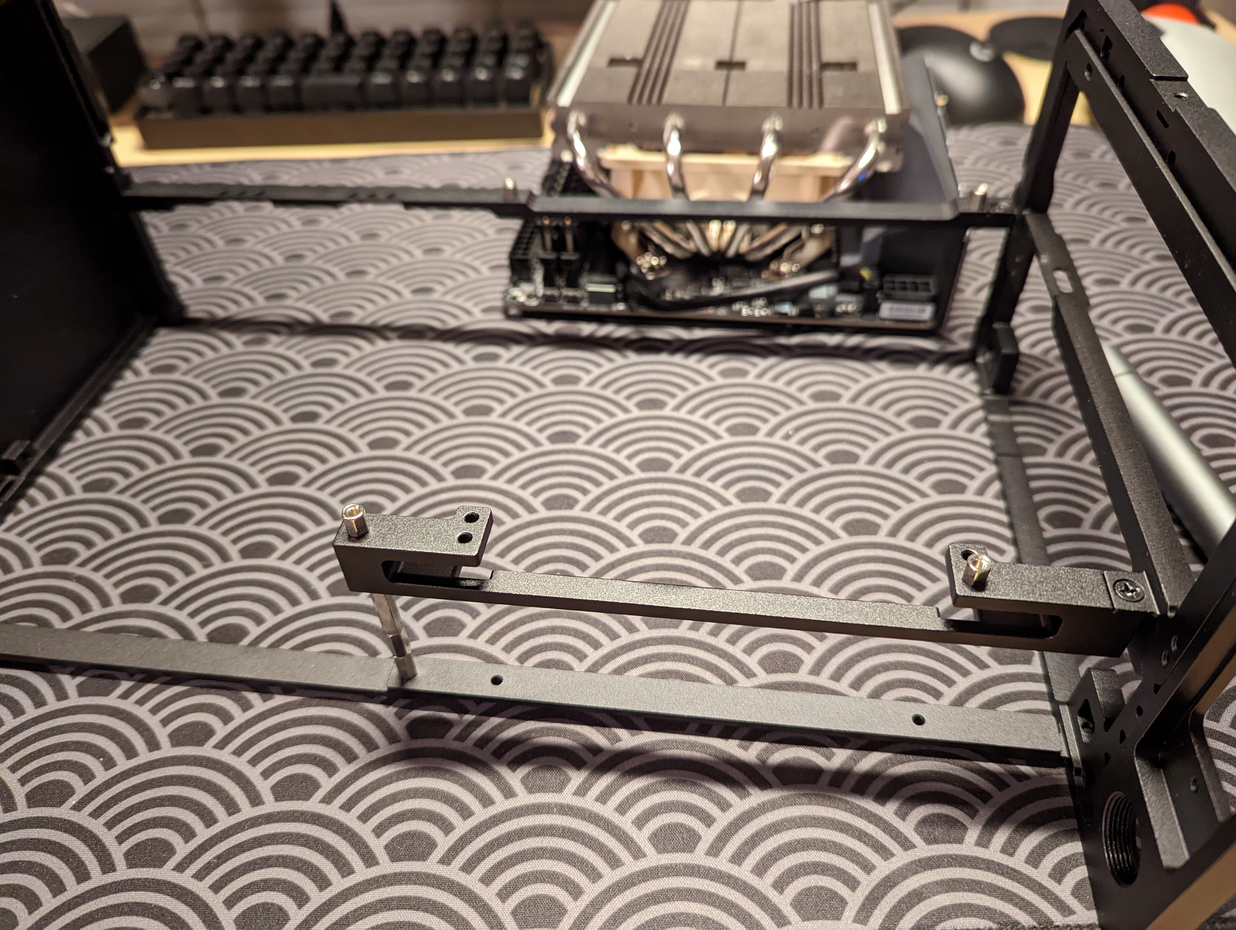
Installing the GPU
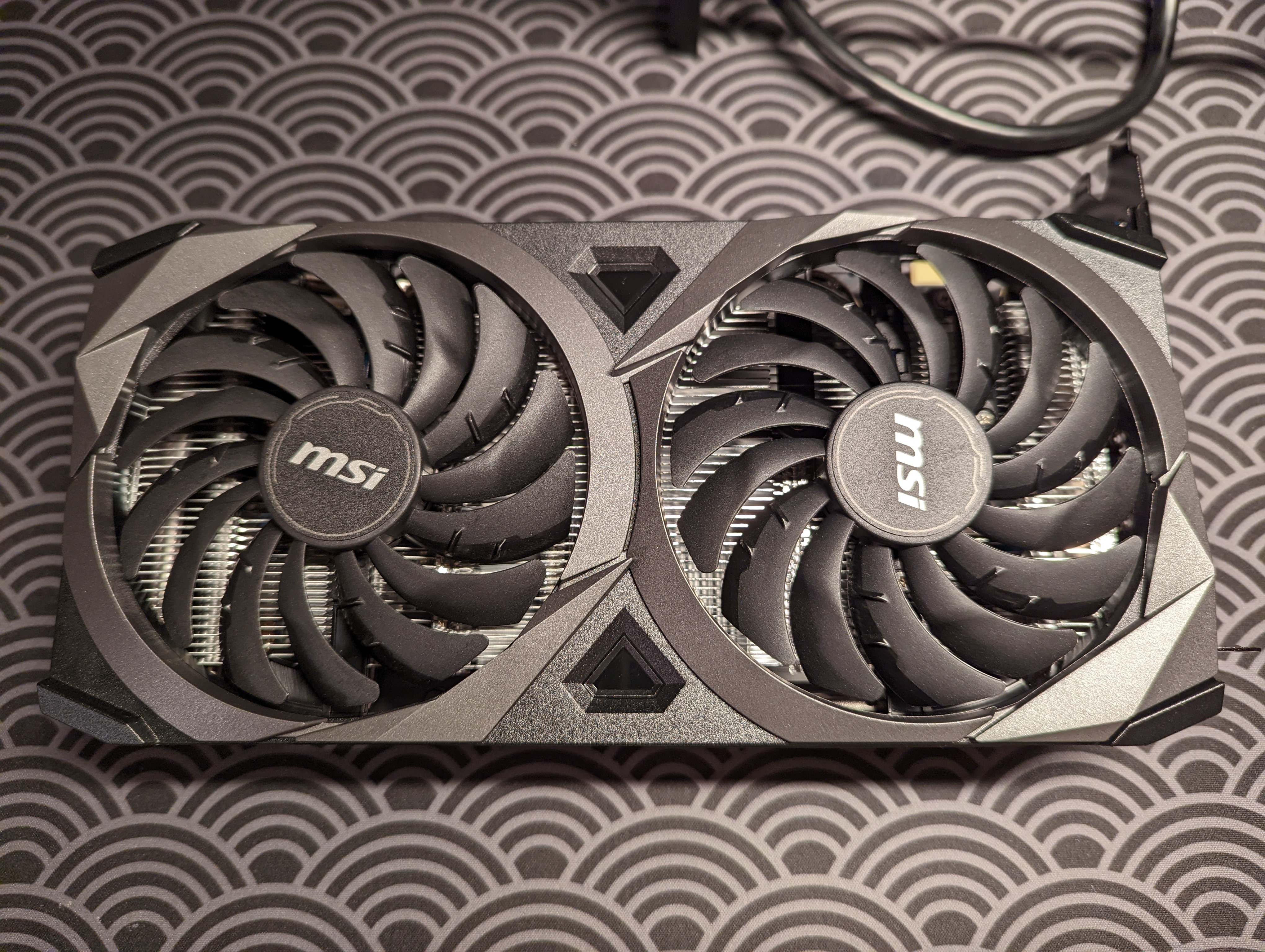
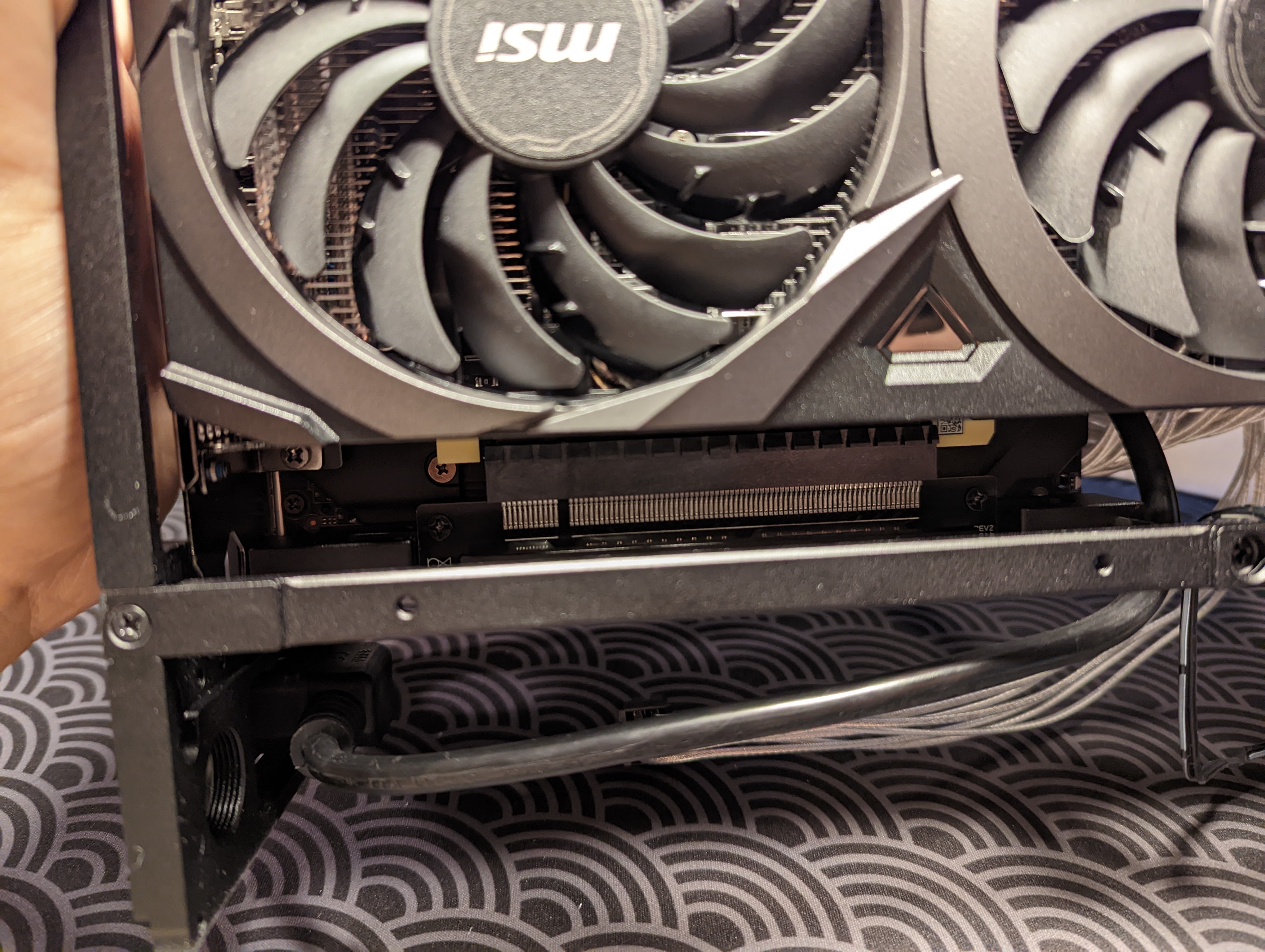
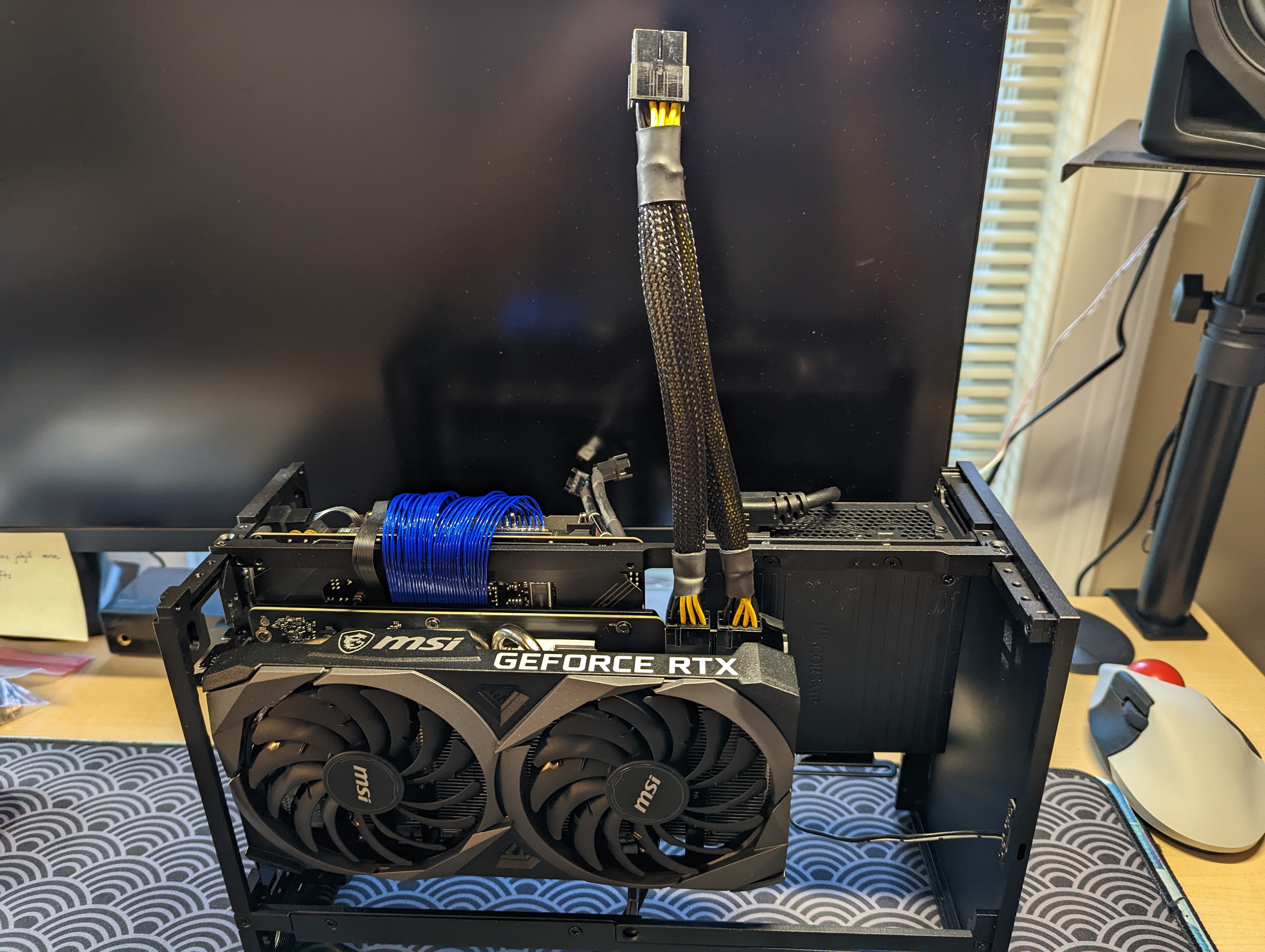
I then install the GPU. I’m using a MSI RTX 3070 Ventus 2X.
30-series GPUs require a PCIe 4.0 connection, so I use a Louqe Cobalt PCIe 4.0 riser cable to connect the GPU to the motherboard. I also use a threaded block that comes with the FormD case to secure the GPU to the PC case.
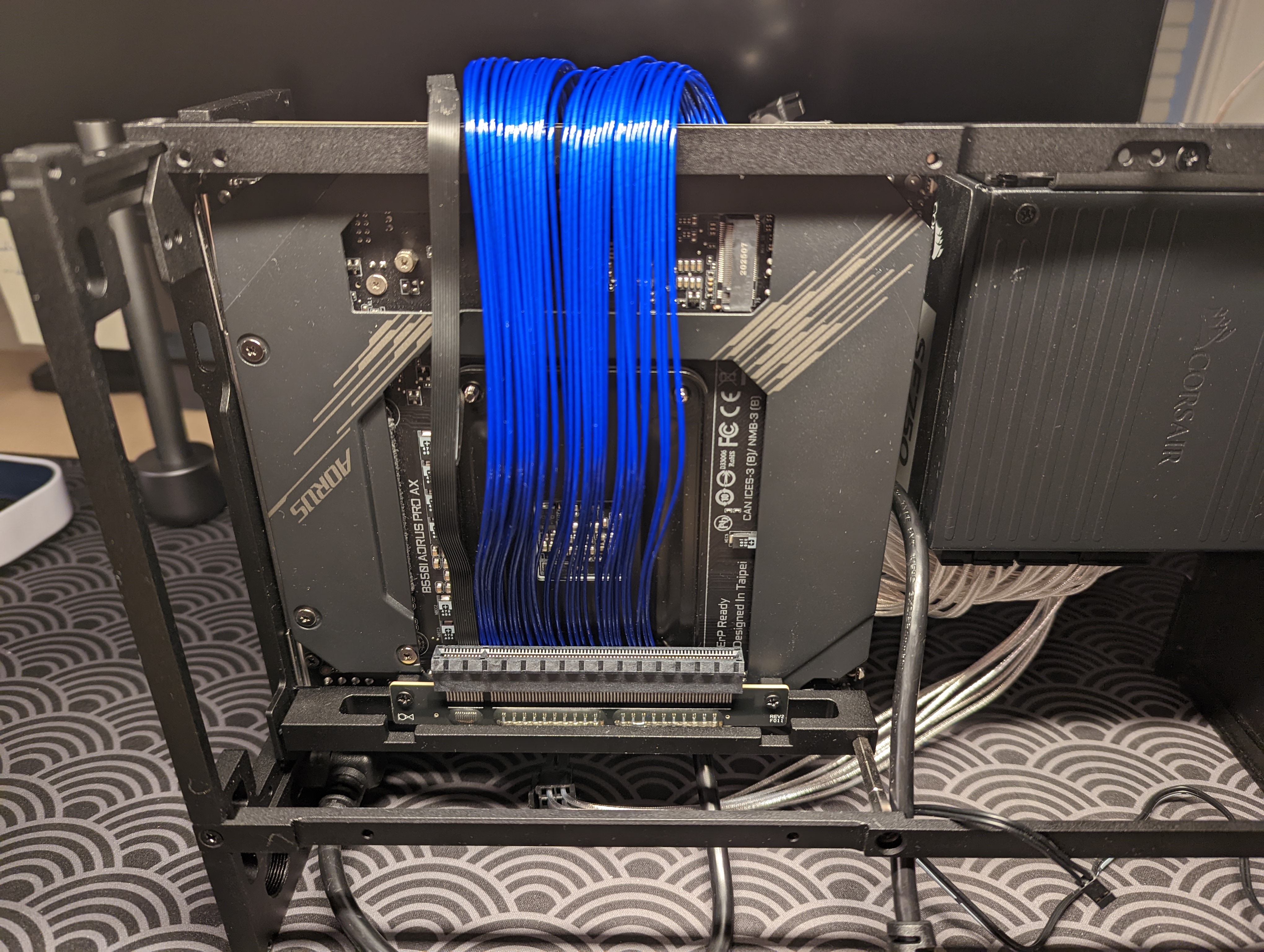
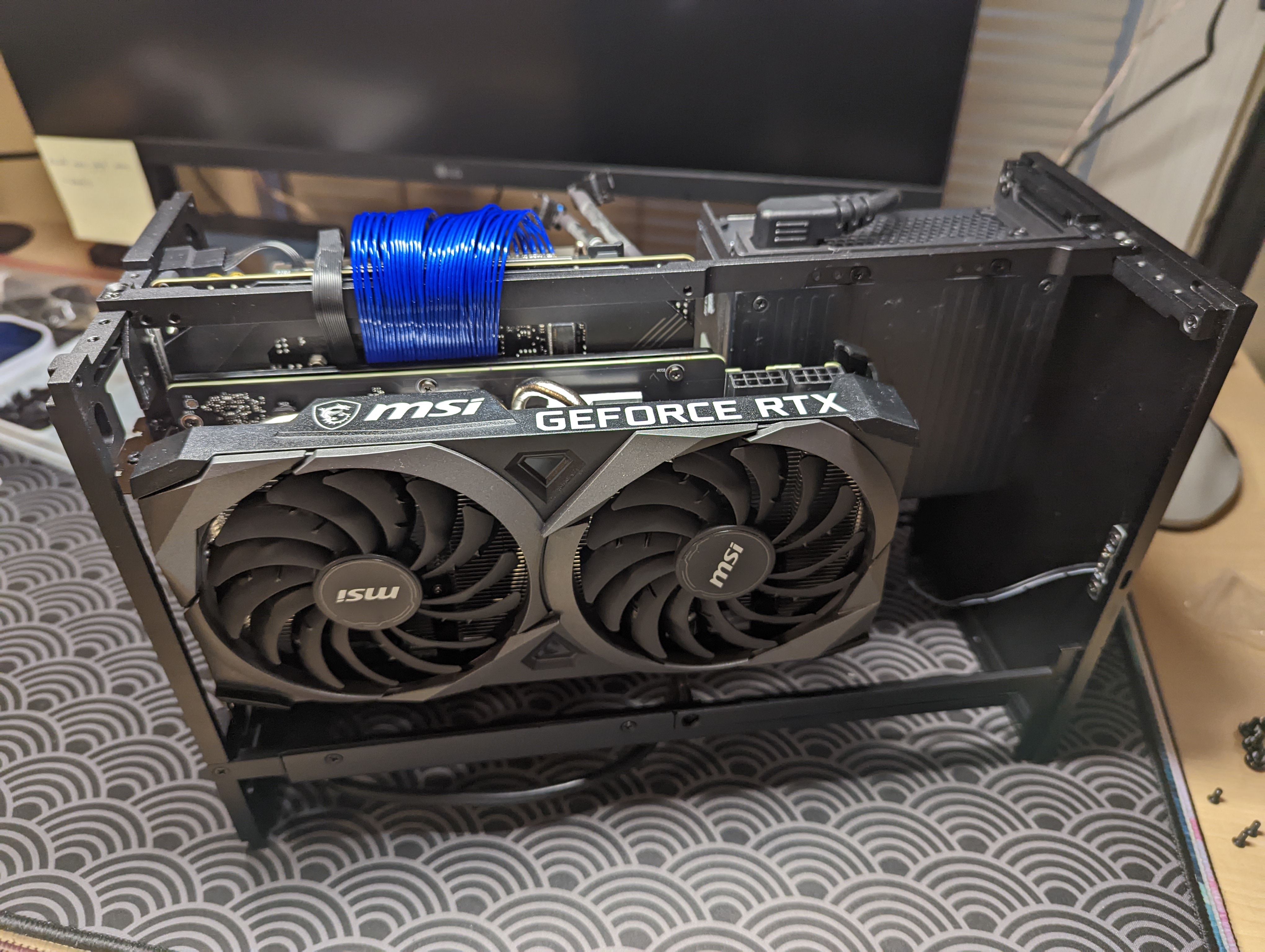
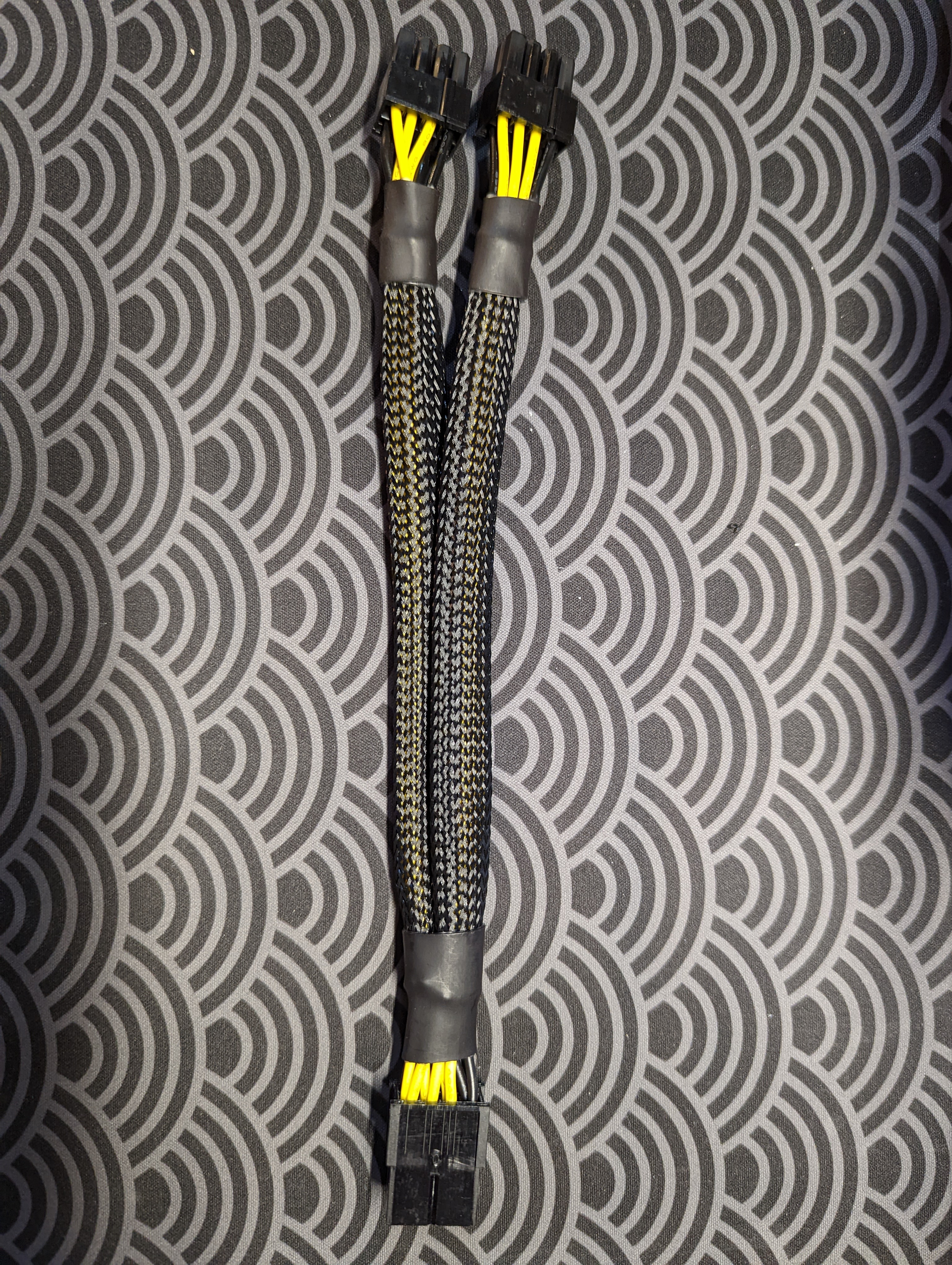
I then plugged in custom-length cables from Pslate Customs into the PSU.
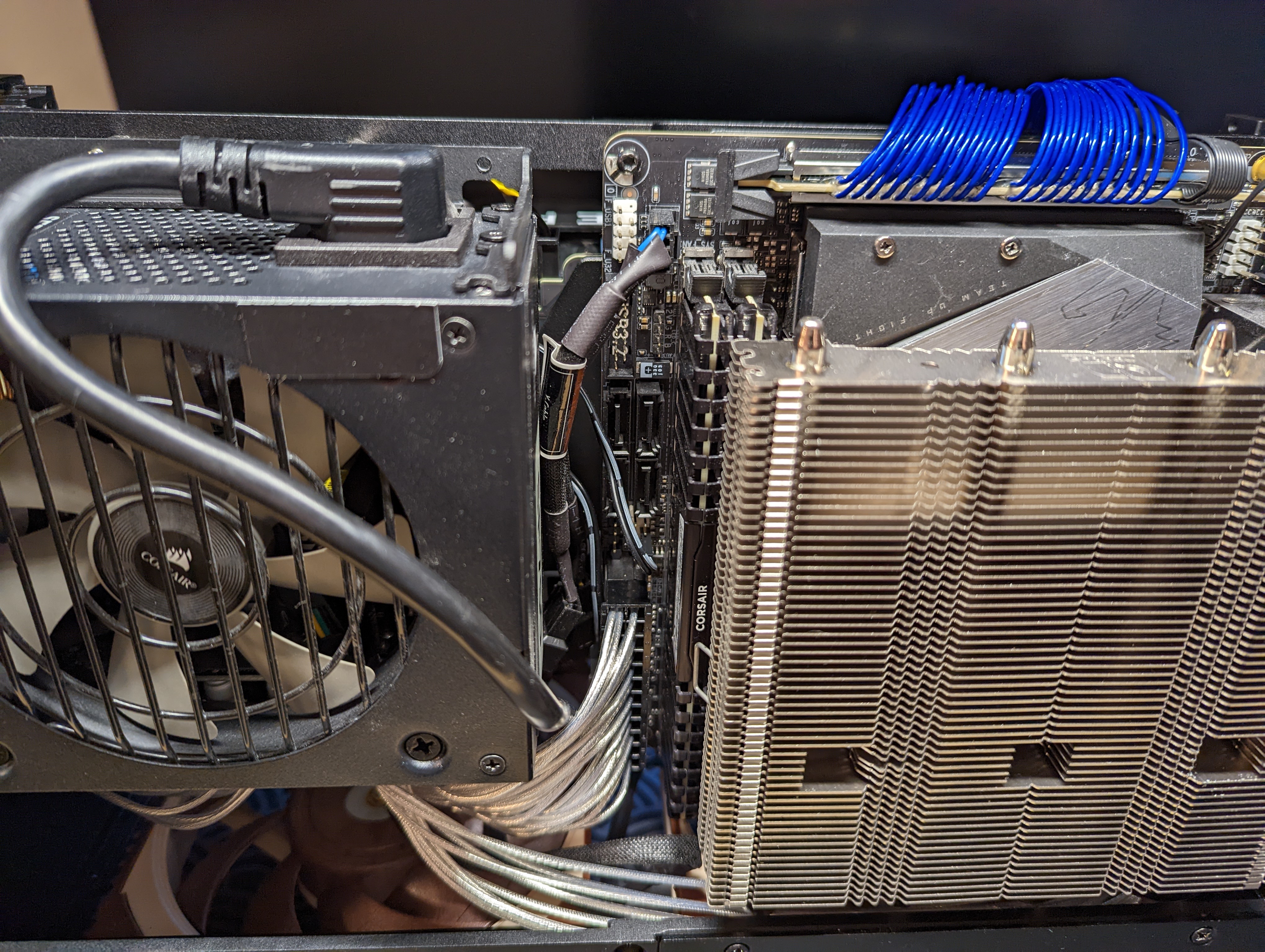
The GPU requires an adaptor that converts a 2x4 pin set into two 2x4 pin sets.
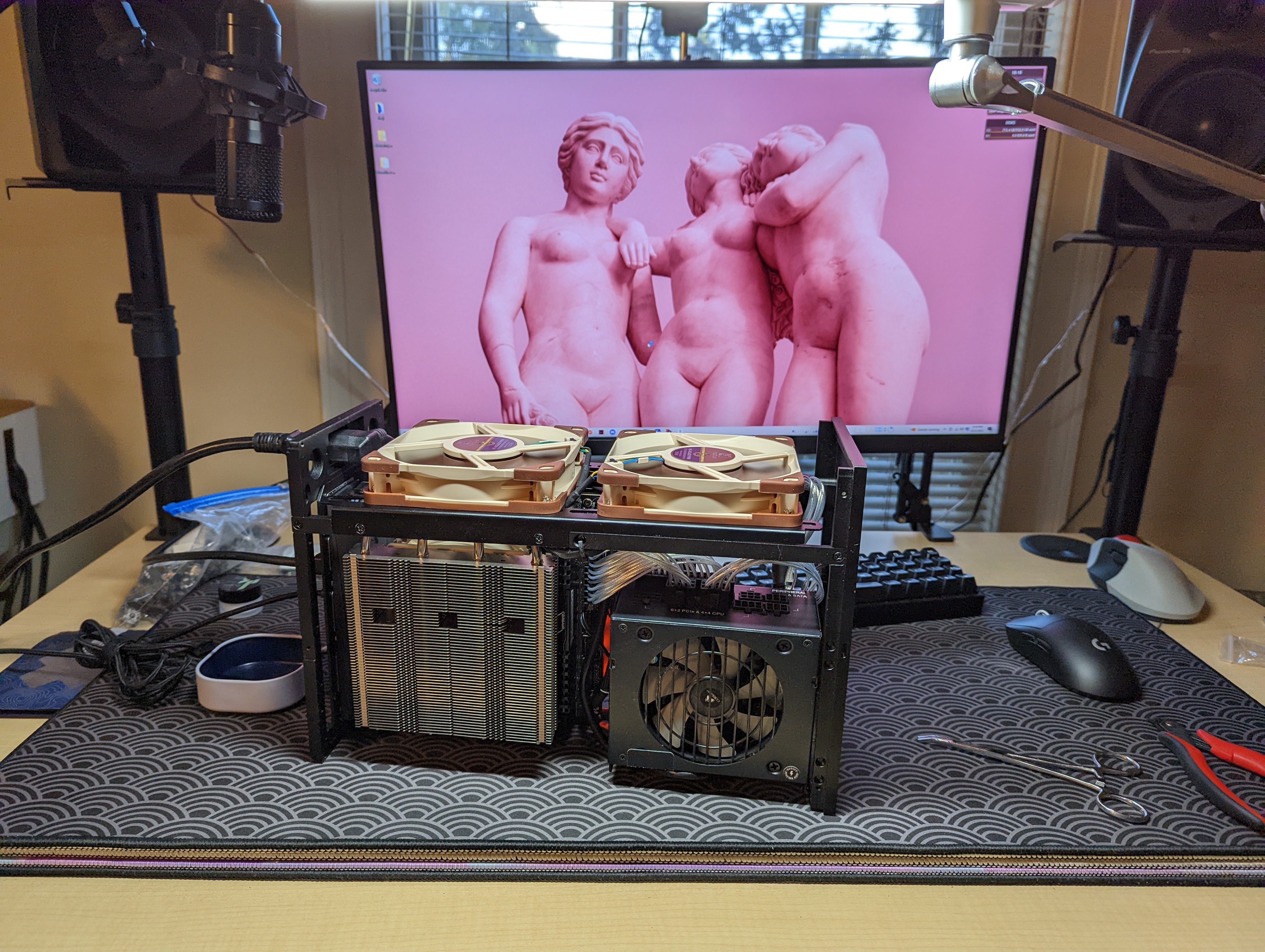
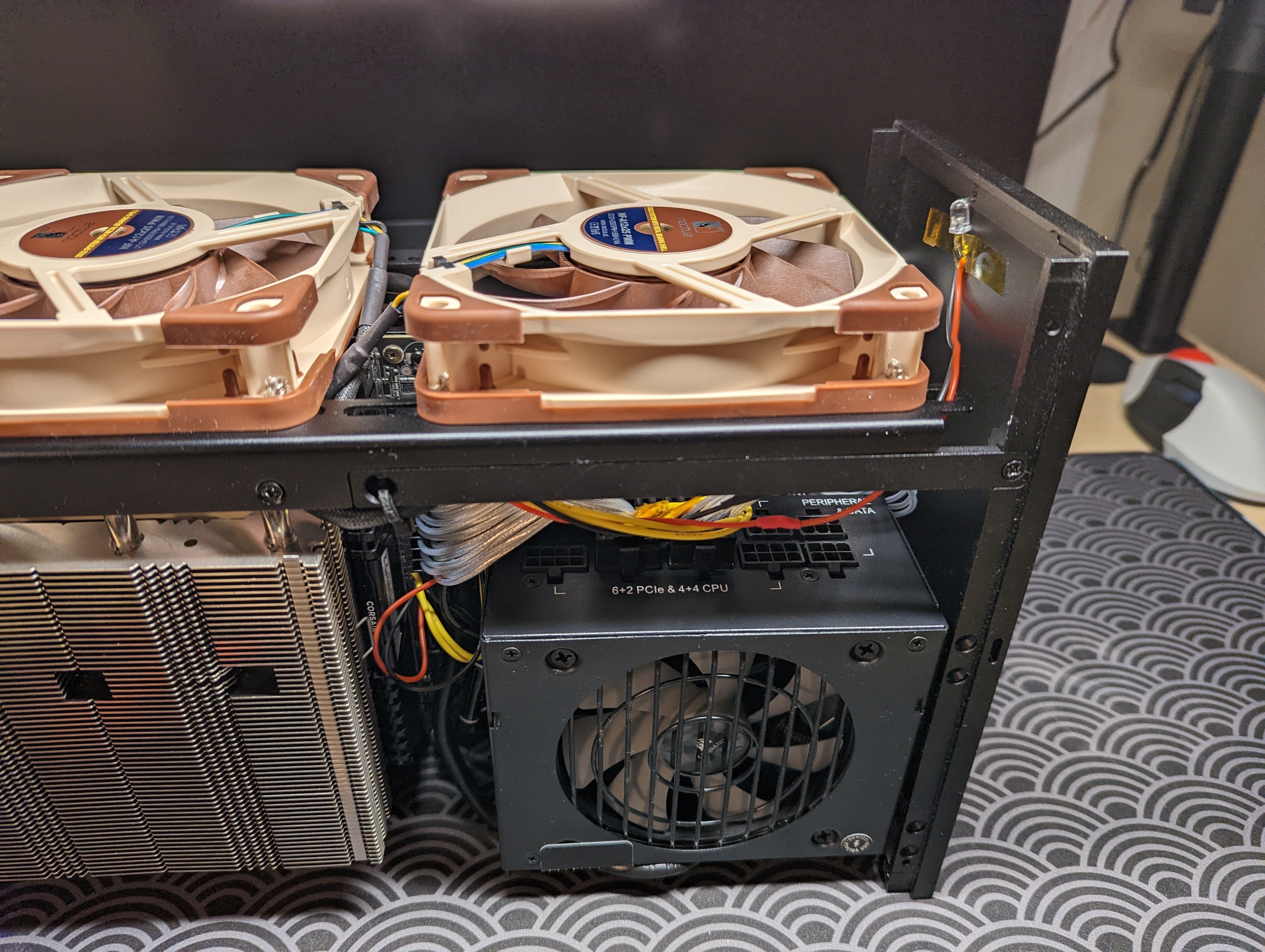
Installing Exhaust Fans
Proper cooling is critical for SFFPC builds. I installed two Noctua NF-A12x25 fans to the top of the case, so that they exhaust hot air from the inside of the PC to the outside. Installing the fans is straightforward. The Noctua fans come with self-tapping screws, and they secure the fans against some slots in the case. The two fans’ cables are connected via a splitter, and the end of the splitter is plugged into SYS_FAN1 on the motherboard. I also used some zip ties to clean up the cabling.
Installing the Power Switch
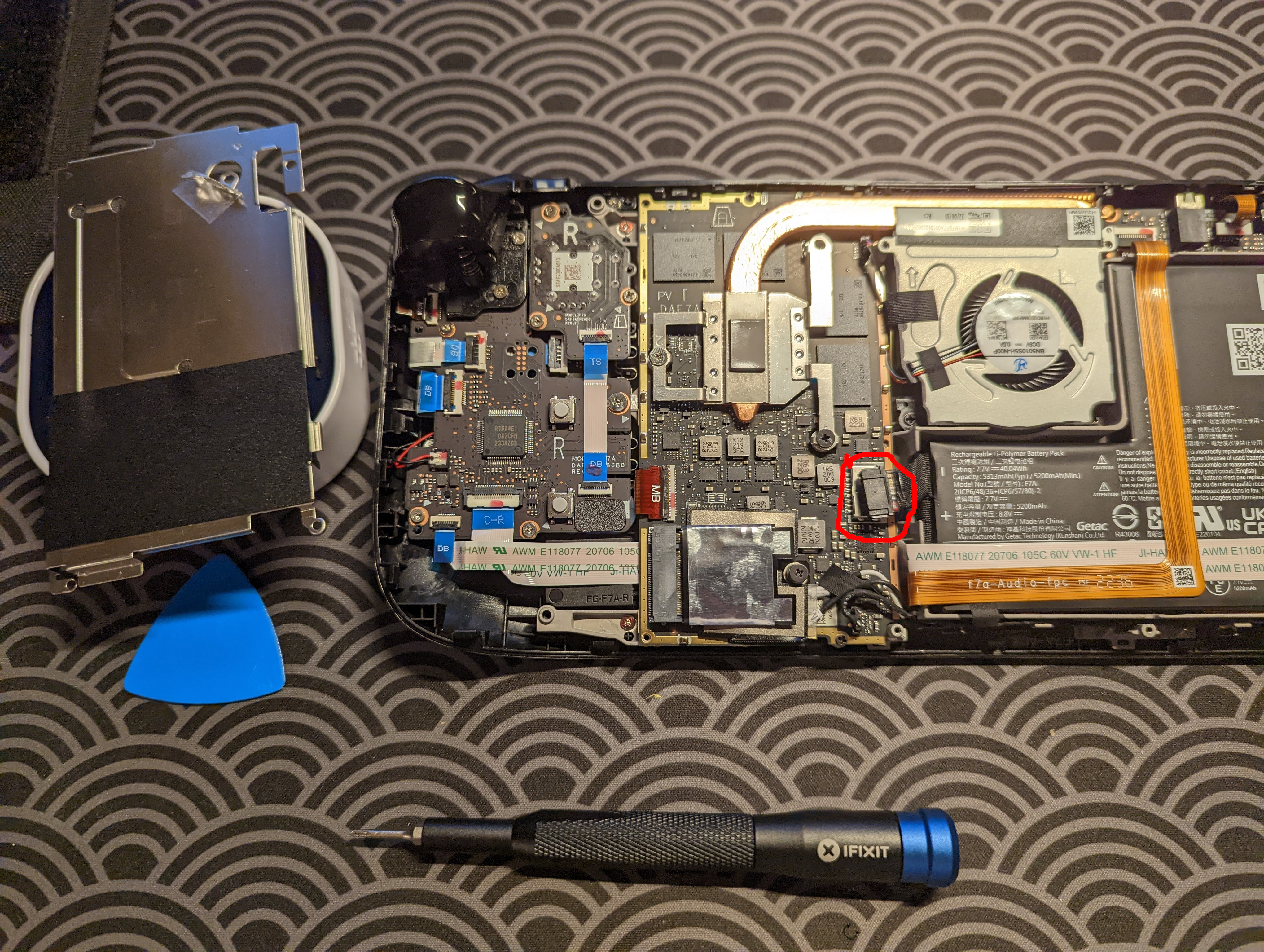
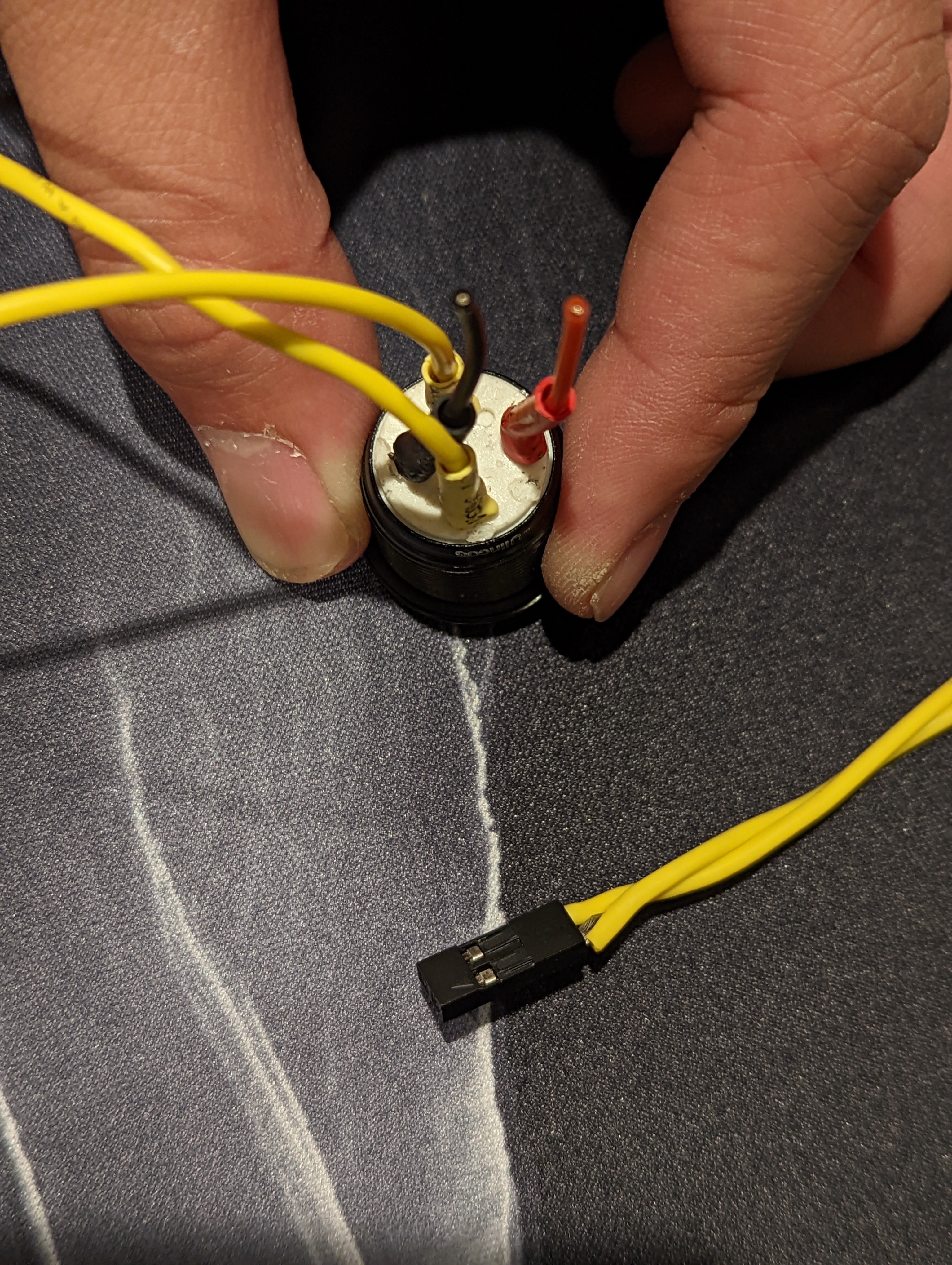
The FormD T1 uses a very discrete button located on the side of the front panel to power on the machine. I find this button really unsatisfying to use, however, and even worse, I’m not always sure whether or not I’ve pressed it, because the button has very little tactility and travel distance. So I instead use this very discrete button as a resest switch, by plugging the leads into the reset pins on the motherboard. The motherboard’s user manual identifies these pins.
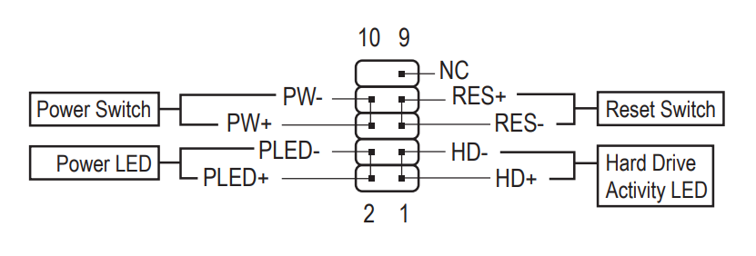
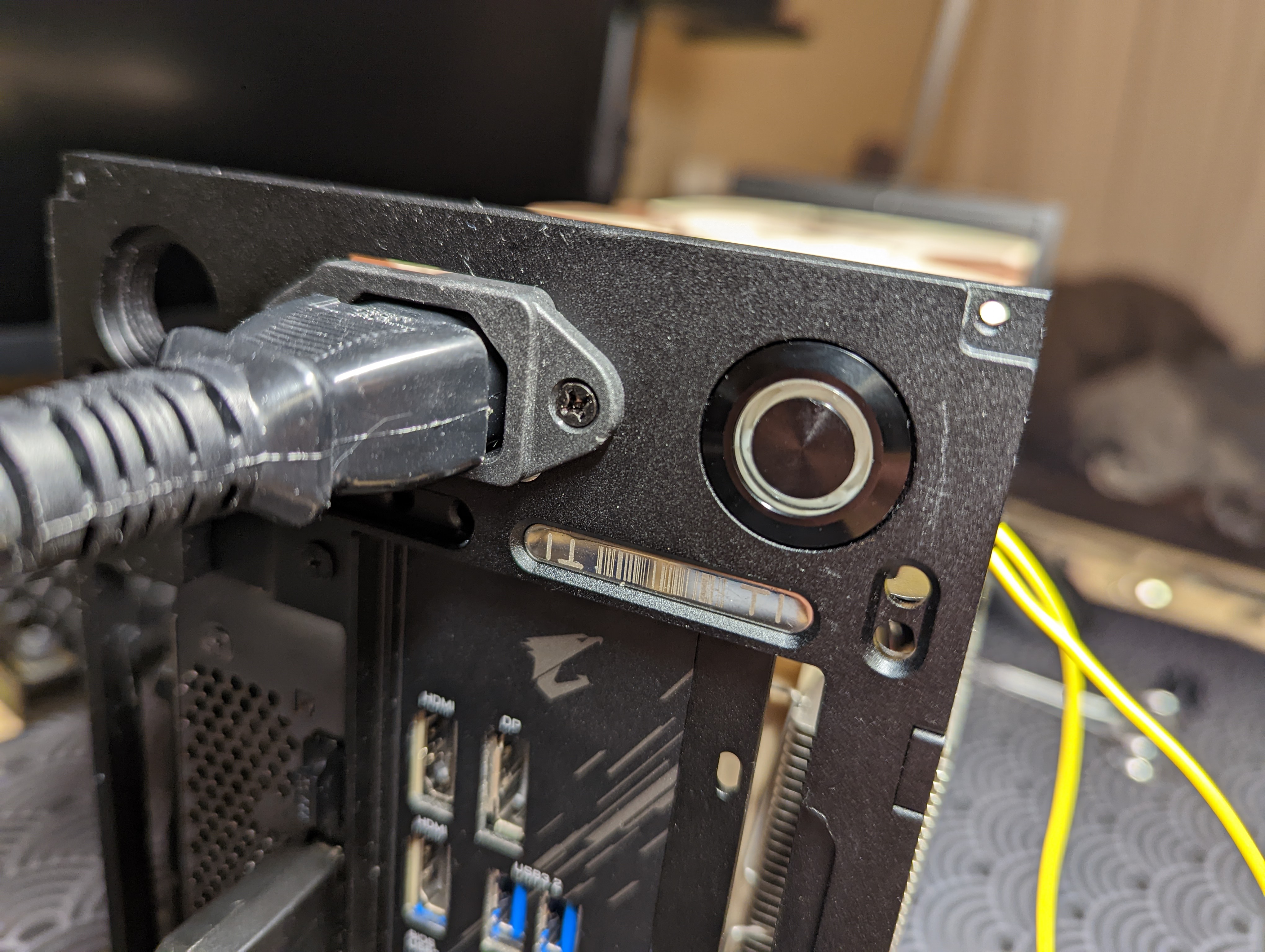
For the power button, I wanted to make use of the big M19 threaded holes at the back of the case. FormD actually sells M19 power switches on their online shop, but it’s frequently out of stock. Fortunately, I found a M19 push button switch on Amazon that works perfectly. The switch is supposed to light up as well, but I couldn’t seem to get the LED working with the LED pins on the motherboard.
Finishing Touches
Even though I couldn’t get the LED that’s built into the push button switch to work, I still wanted a power status LED. Fortunately, I have a bunch of LEDs lying around. I wired up a white LED to the motherboard’s Power LED pins, and I Kapton taped it to the inside of the PC case’s front panel.
Finally, I wanted to do something about the other M19 threaded hole that’s gaping open at the back of the case. The case has two M19 holes, and I used the power switch to cover one of the holes. Fortunately, FormD suplies .stl files for 3D-printing threaded caps that can cover the M19 holes. I found the dimensions of the threaded cap to be a little too snug, however, so I adjusted the file’s x and y scaling in Prusa Slicer to 98%. With this slight adjustment, the print came out perfectly.
Fan Configuration
The PC is totally usable now! We can use it for all sorts of things, including more intense workloads like video games, CAD, and video editing work. Before we call it a day though, we’re going to want to configure the fans. SFFPCs are small, and so they can build up a lot of heat inside the computer. We want to try and optimize the computer’s cooling performance.
By default, fans that are plugged into the motherboard will ramp up based on CPU temperature. So, the Noctua exhaust fans we installed will ramp up as the CPU temperatures get higher. We don’t want this relationship, however. Instead, we want our exhaust fans to ramp up as the GPU temperatures get higher. To estbalish this relationship, we have to use a program called Argus Monitor. Optimum Tech shows how to use this program in this video at 20:59.
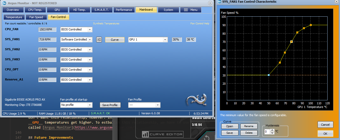
SYS_FAN1 via a fan splitter. So we have one fan port controlling two fans.
GPU Undervolting
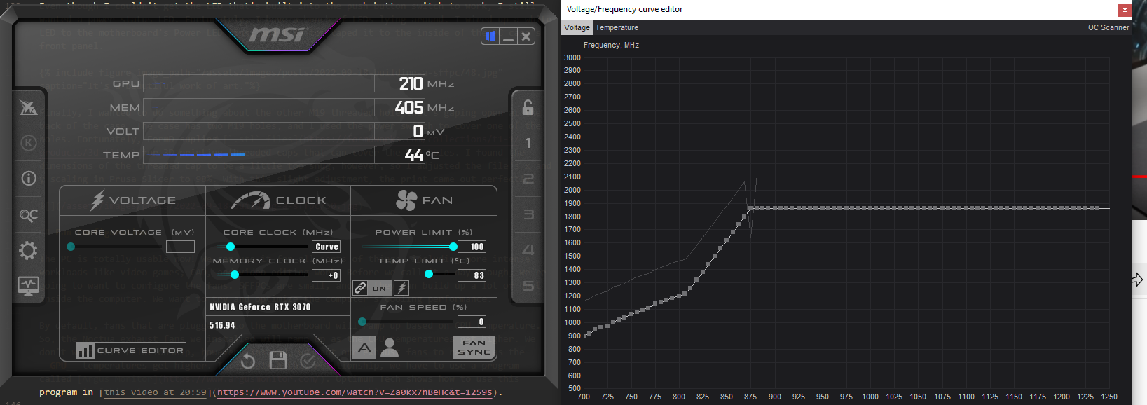
Everyone in the SFFPC world recommends undervolting the GPU. Undervolting the GPU results in quieter and cooler operation, with no cost to performance. Again, Optimum Tech explains how to undervolt the GPU in this video at 21:36. We use a software called MSI Afterburner to undervolt the GPU.
Future Improvements
All in all, I’m very happy with the build! I think the only thing I might want to add in the future is a front IO panel.
Parts Summary
| Item | Part |
|---|---|
| Case | FormD T1 Sandwich Kit |
| PSU | Corsair SF750 power supply |
| CPU | AMD Ryzen 9 3900X |
| CPU Cooler | Noctua NH-L12 (Ghost S1 Edition) |
| Motherboard | Gigabyte B550I Aorus Pro AX |
| RAM | Corsair Vengeance LPX 64GB (2 x 32GB) DDR4 DRAM 3200MHz |
| SSD | Samsung 970 Evo Plus 1 TB |
| GPU | MSI RTX 3070 Ventus 2X |
| PCIe riser | Louqe PCIe 4.0 riser cable |
| Exhaust Fans | Two Noctua NH A12x25 fans |
| Power Switch | Ulincos Momentary Pushbutton Switch U19D1 1NO SPST for 19 mm mounting hole |
Footnotes
-
You can still build very poweful computers in ITX cases, without creating the world’s desnsest space heater. In many ways, the engineering challenge of trying to build the most powerful computer in the smallest space is what draws people into the SFFPC world. People have come up with clever ways of efficiently disippating heat from even the most power hungry hardware. ↩