Not too long ago, I purchased a Libra Mini from AliExpress, and I absolutely love it. The only problem is that it’s row-staggered like a traditional keyboard … but I liked the Alice-esque monoblock style, as well as the tenting. so I went about looking for a column-staggered board with those features. I couldn’t find a tented column-staggered keyboard1, but I did find some promising ‘split’ monoblock style boards, like the babyV by Eye Oh Designs, and the Faux Fox or FFKB by Fingerpunch. I thought both these boards looked really nice, but I was really smitten by the FFKB. It can support a Cirque trackpad in the middle, as well as both EC11-style and EVQWGD001-style rotary encoders. I can also use a Nice!Nano (v2) as the µC and ZMK firmware, to make the keyboard wireless. In this post, I document my build of the FFKB (V2).
Case
One of the awesome things about the FFKB keyboard is its incredible modularity. You can add all sorts of different kinds of rotary encoders, or an OLED screen, or a trackpad, or hardware functions for a wireless build (e.g. a hardware power switch), or low pro or regular mechanical swtiches. To accommodate for all this modularity, a few case options are available on Sadek’s GitHub. I’m building with hot swap choc low pro switches, EVQ11 rotary encoders, a Cirque trackpad, and wireless functionality. The corresponding case for these hardware features is this top case and this bottom case. The top case has “mx” in its title, but in this case, the “mx” just denotes that the case is tall enough to accommodate for regular LiPoly battery thicknesses.
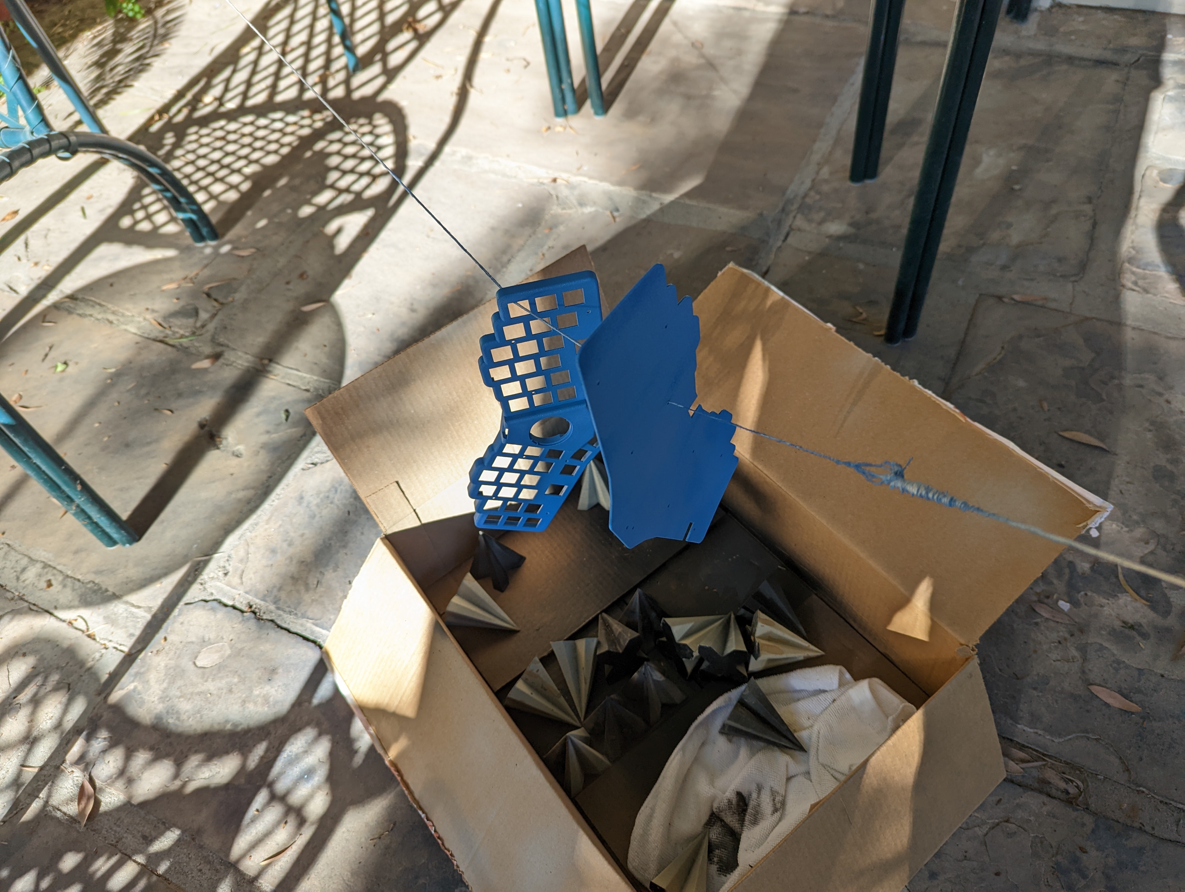
I got my case parts printed in white nylon from PCBWay. I then tried my hand at spray painting the case parts! I used some twine to hang the parts in midair, and I placed a cardboard box underneath, so no off-target paint would reach the patio floor. I’m using a Rust-Oleum Satin Wildflower Blue spray can that I picked up from Home Depot. This paint colour sprays very smoothly and evenly, and is very easy to use.
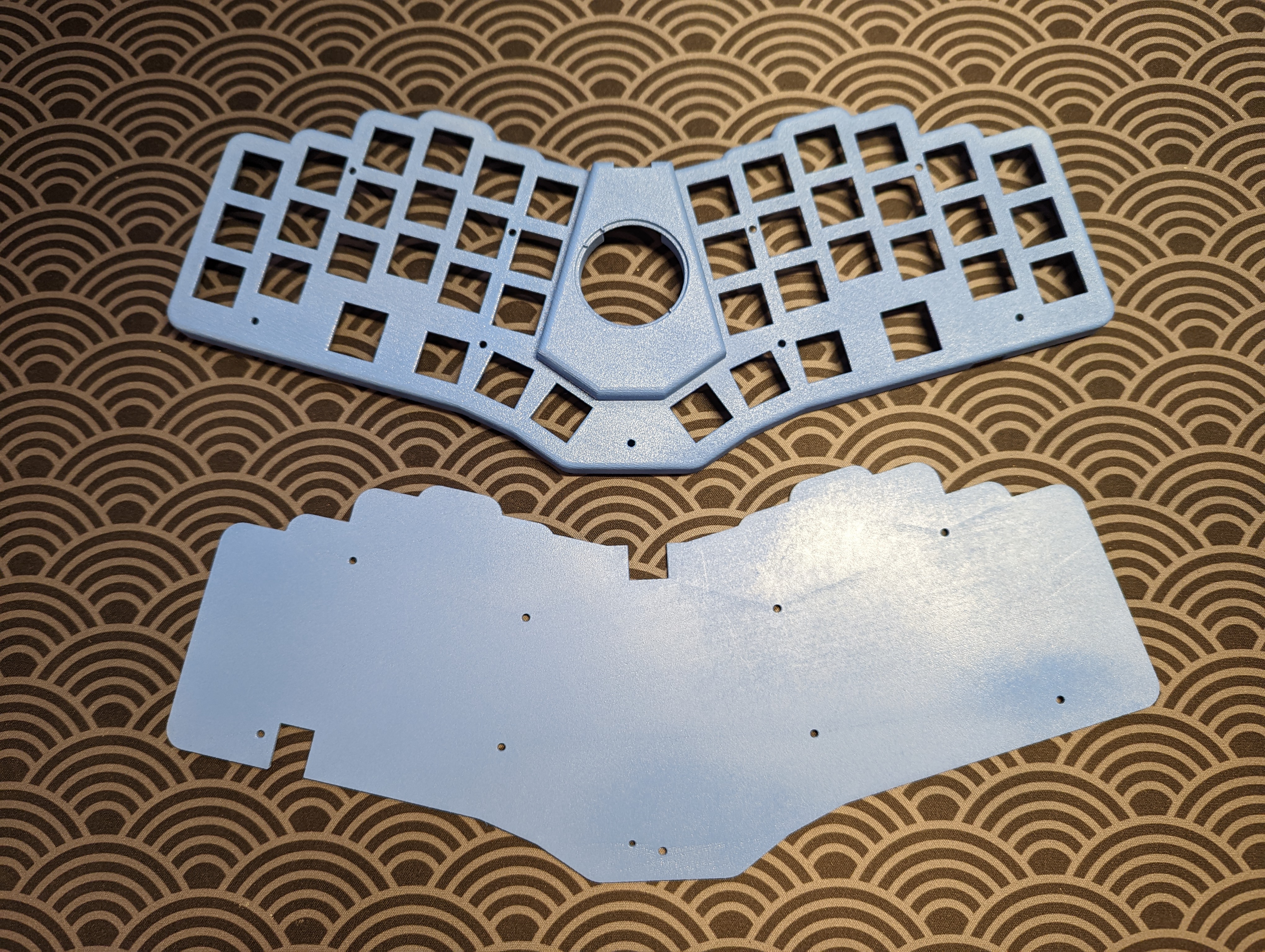
After 4 layers, I managed to cover all the case parts. I think the end result looks pretty good!
Electronics
-
Solder the hot-swap sockets. I plan on supporting hot swap low pro Choc switches, so I solder low pro Choc sockets to the bottom of the PCB. The bottom of the PCB features a reset button.
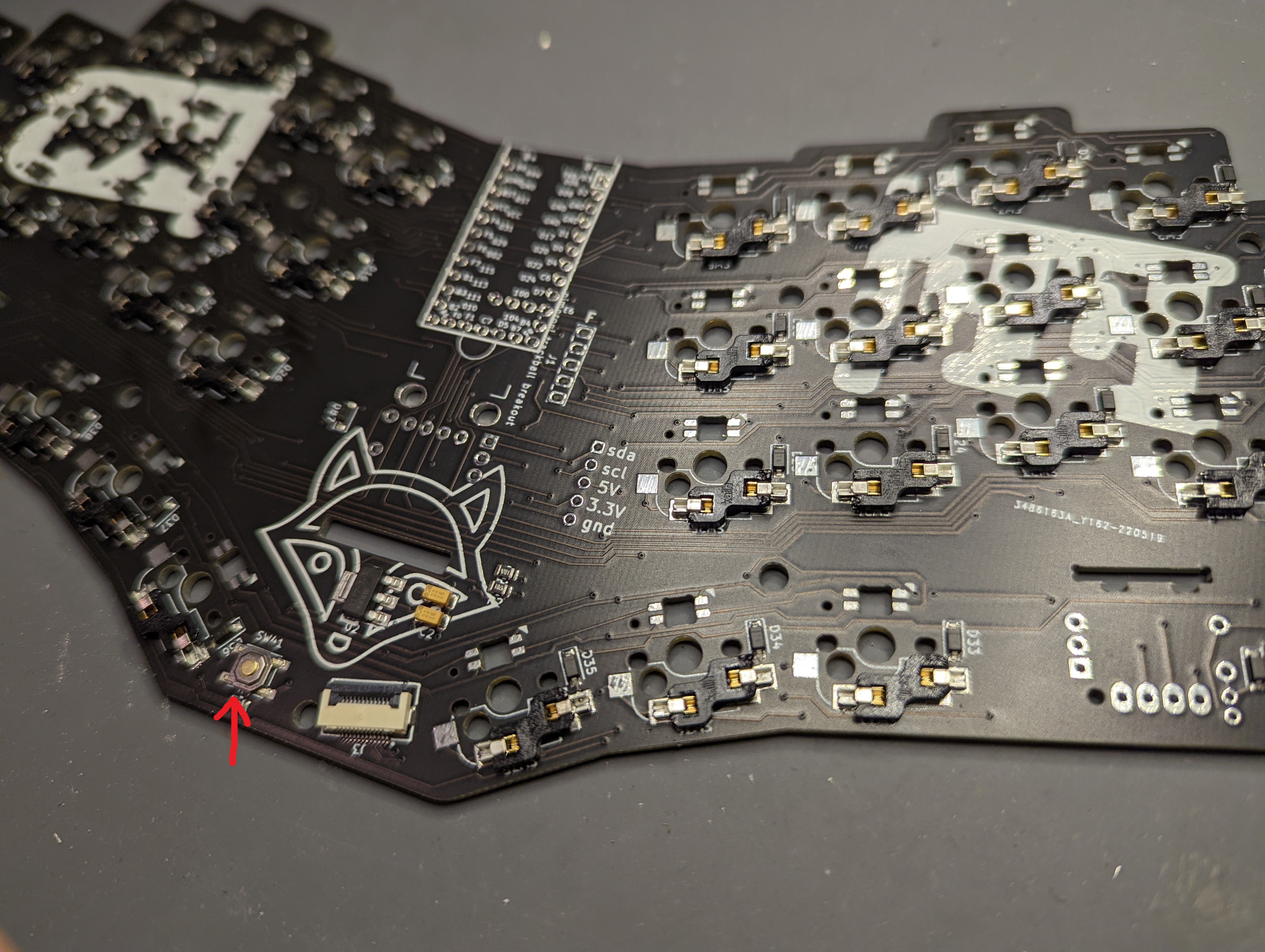
A reset button denotes the bottom side of the PCB, which I’ve marked with a red arrow. -
Solder the µC to the PCB. The bottom of the PCB features a reset button. We want to solder the µC to the top side of the PCB. If you plan on socketing the µC, make sure you use one of the thin Mill-Max sockets, or else the µC’s USB port will not fit in the case.
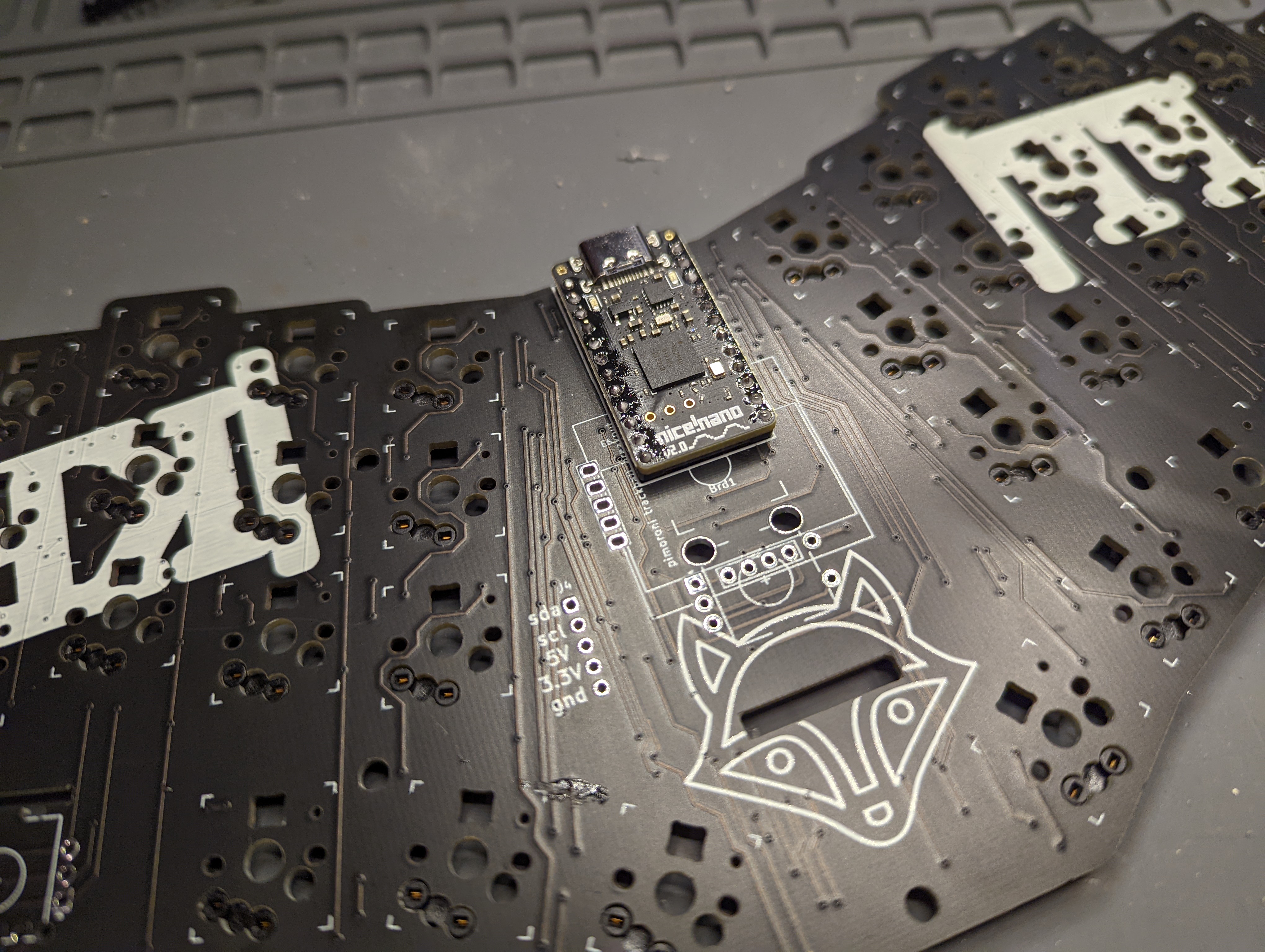
Solder the µC, or if applicable, the socket, to the top side of the PCB. I’m using a Nice!Nano as my µC, so I need to solder an extra set of 1 x 3 headers to the PCB, as specified in the official docs.
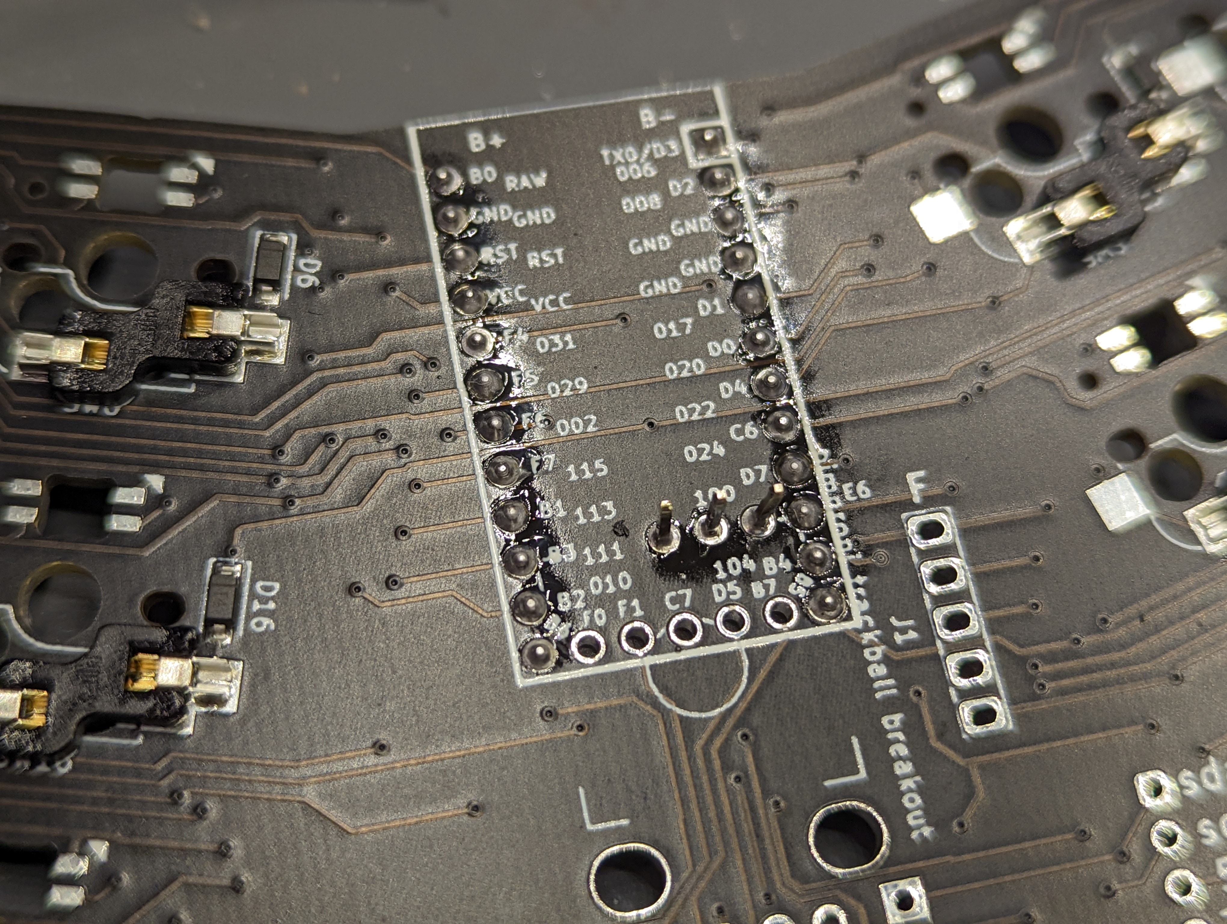
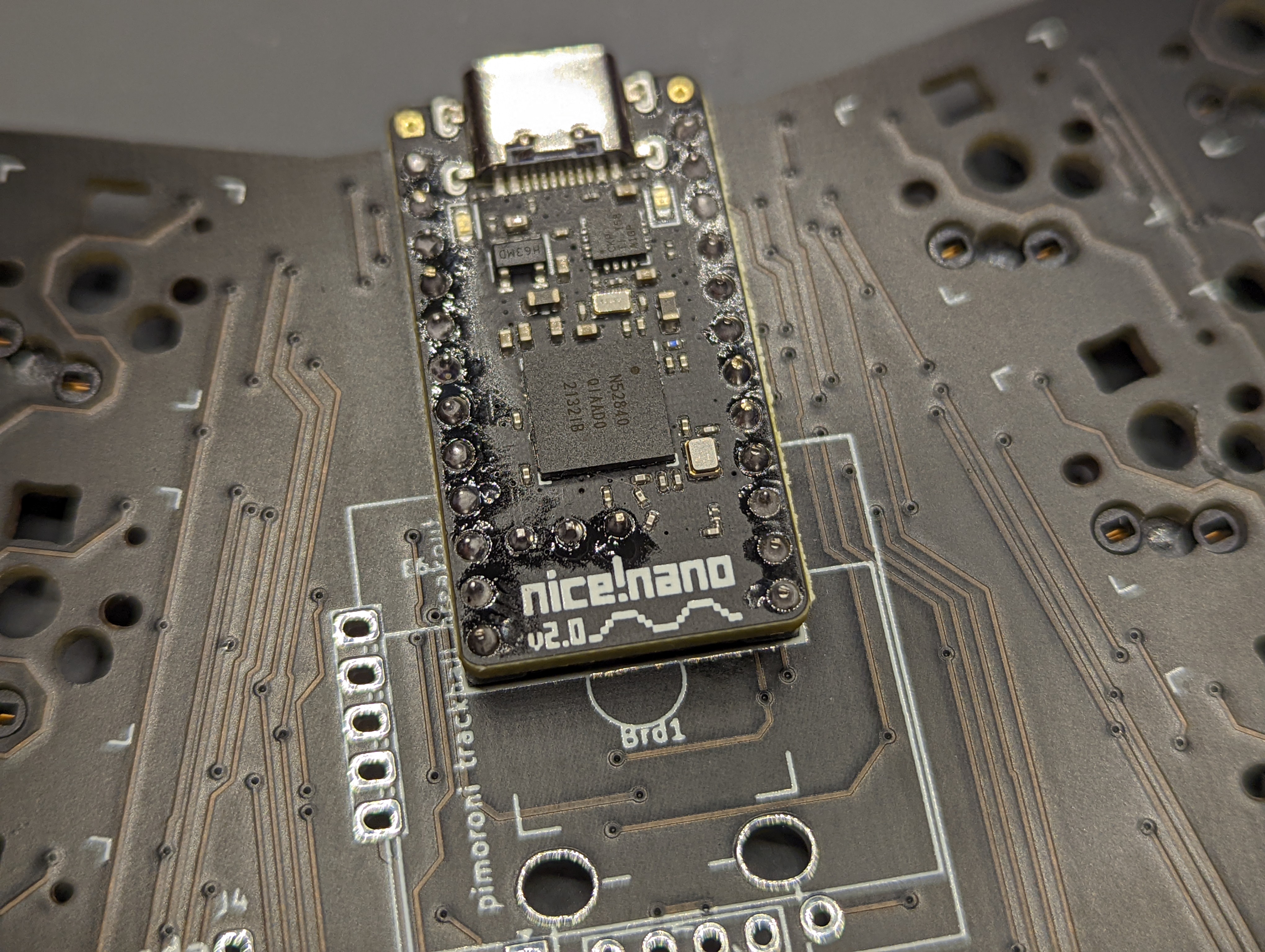
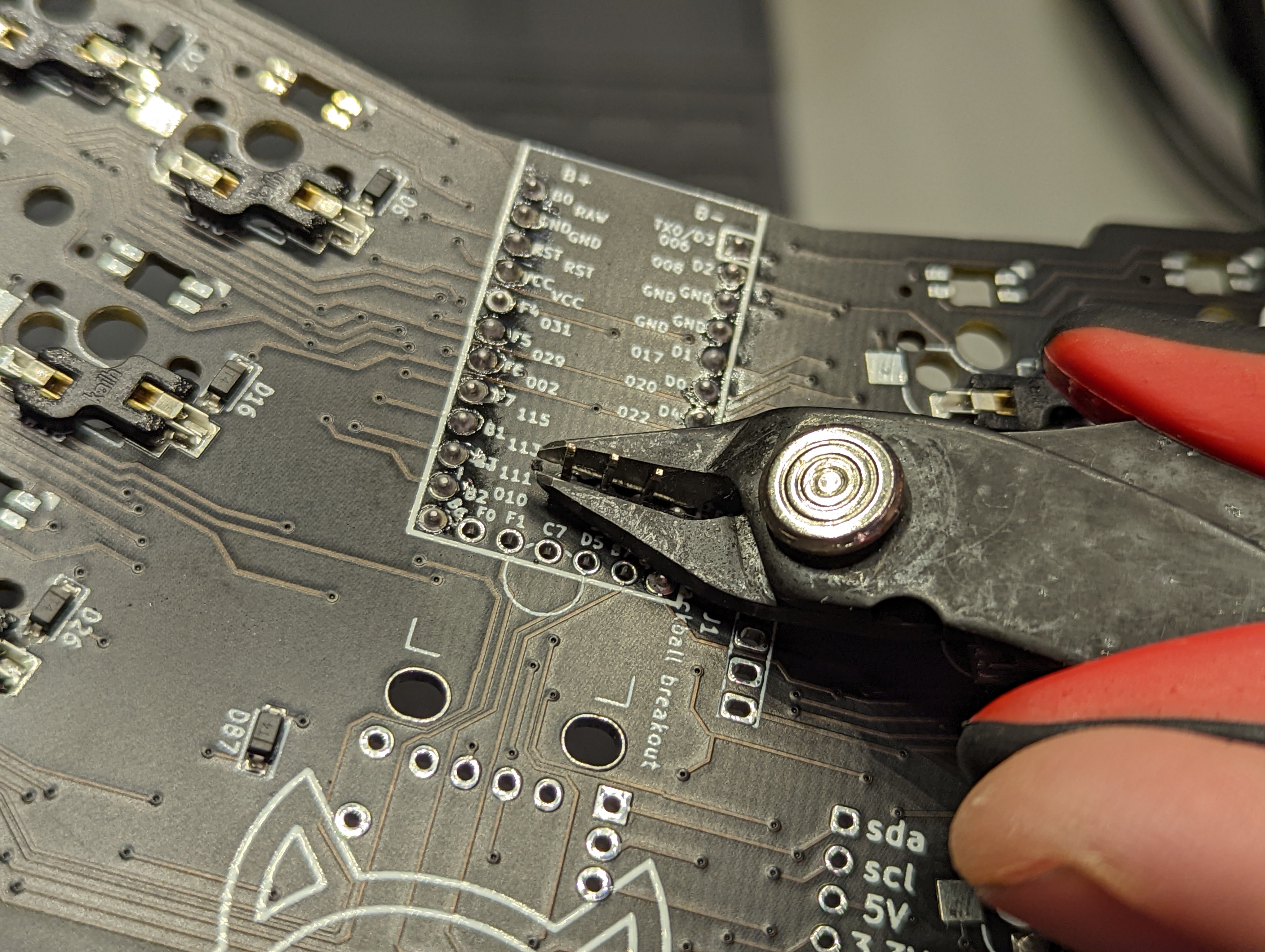
For the Nice!Nano, solder another 1 x 3 header pins onto the µC. Clip off the excess header pins. Note that even though I socketed the µC, the socket I used doesn't support the extra 1 x 3 pins I soldered here. So, removing the µC from the main PCB would require me to desolder the 1 x 3 pins, but I wouldn't need to desolder anything else. -
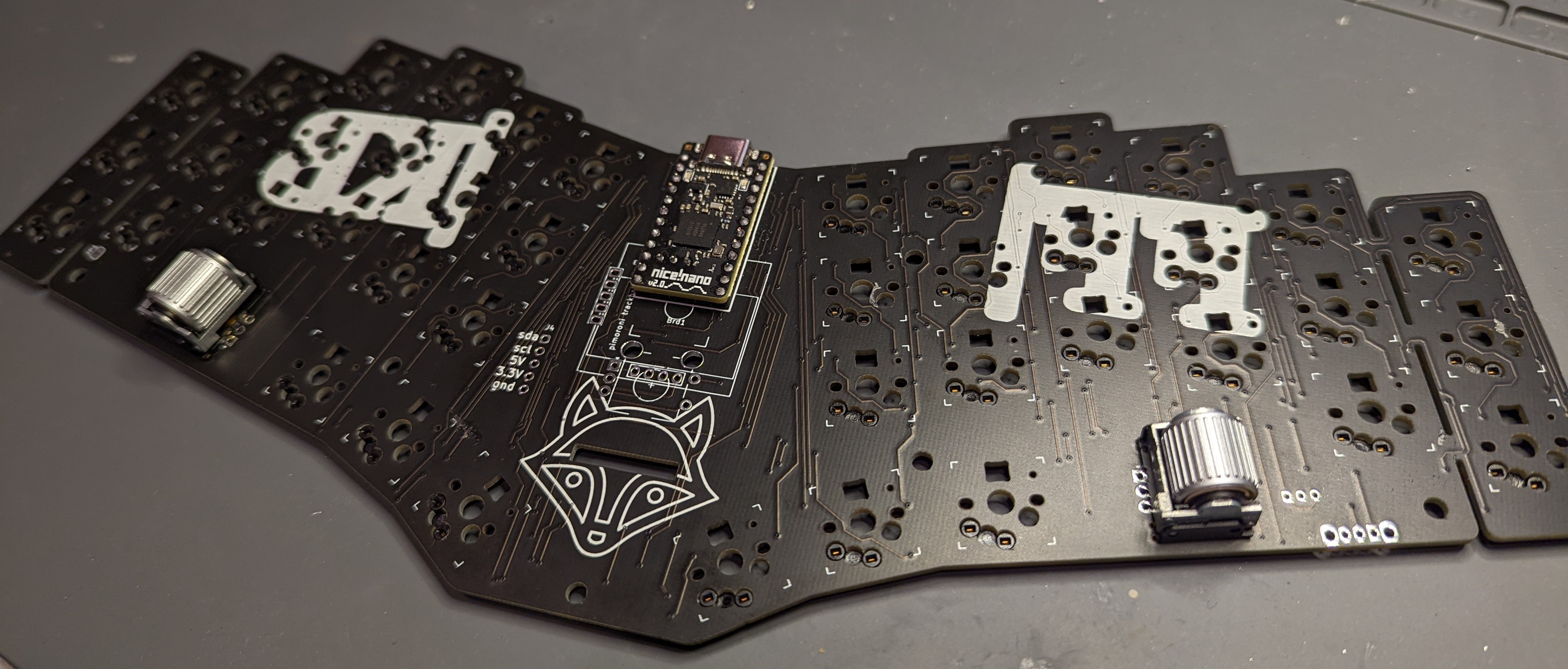
Solder the rotary encoders. I’ve always wanted to use EVQWGD001-style rotary encoders, and now’s my chance! I solder the rotary encoders to the top of the PCB. In the future, I’ll probably try and design my own keyboard, or handwire something, that supports these cool and very ergonomic encoders.
-
Connect the Cirque trackpad. Here’s the really fun part! The FFKB (v2) is pretty cool in that the Cirque trackpad spot can be replaced with a different feature, such as an OLED screen, or an EC11 rotary encoder. I’ve opted for the Cirque trackpad, because I’ve seen many keyboards support OLEDs and rotary encoders, but I’ve rarely seen one that supports a trackpad.
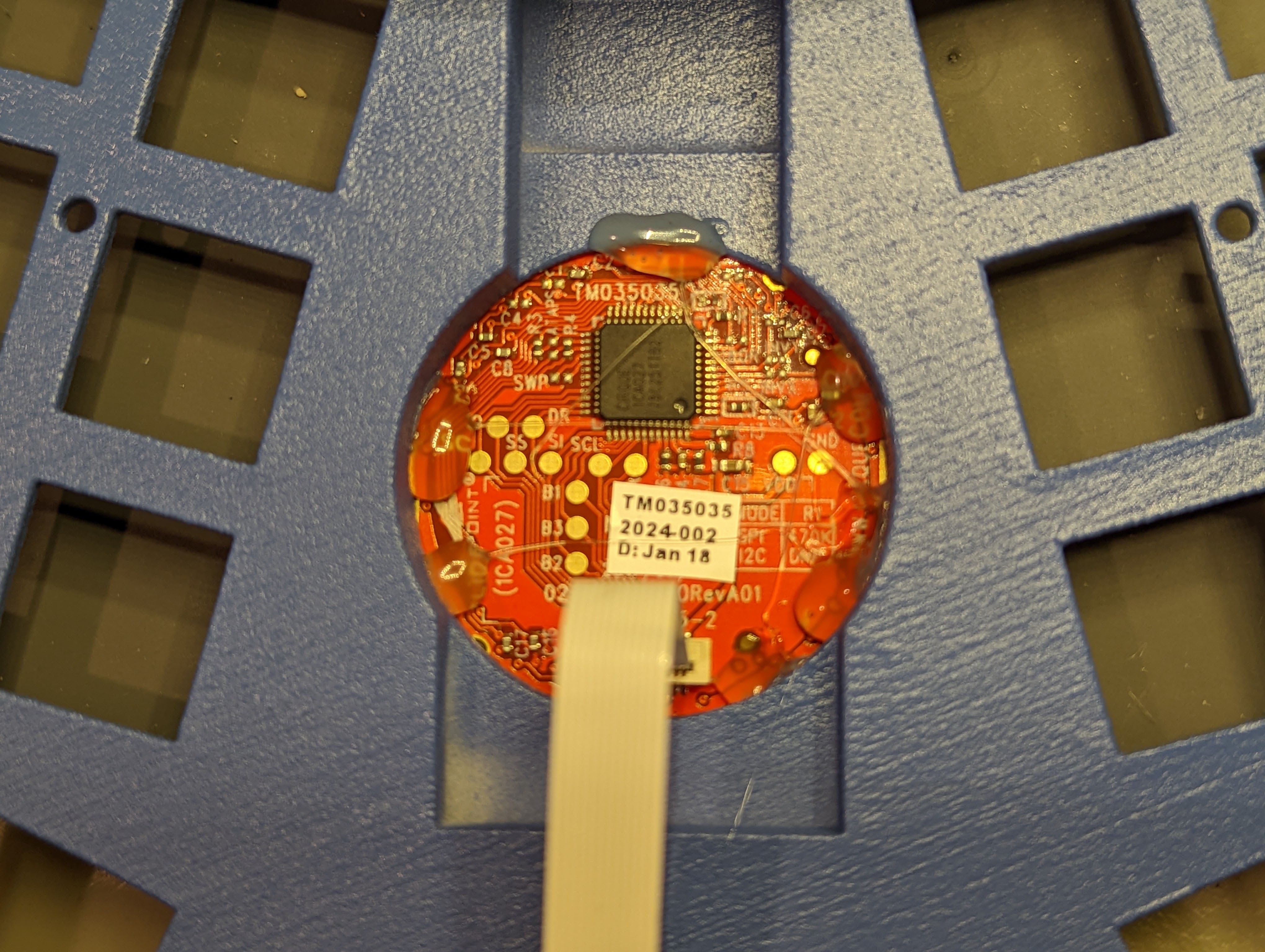
We first have to make sure that the R1 resistor is removed from the back of the trackpad, so the trackpad’s I2C protocol is enabled. In my case, the R1 resistor was already removed! Presumably, Sadek, the founder of Fingerpunch, already did this step for me
 .
.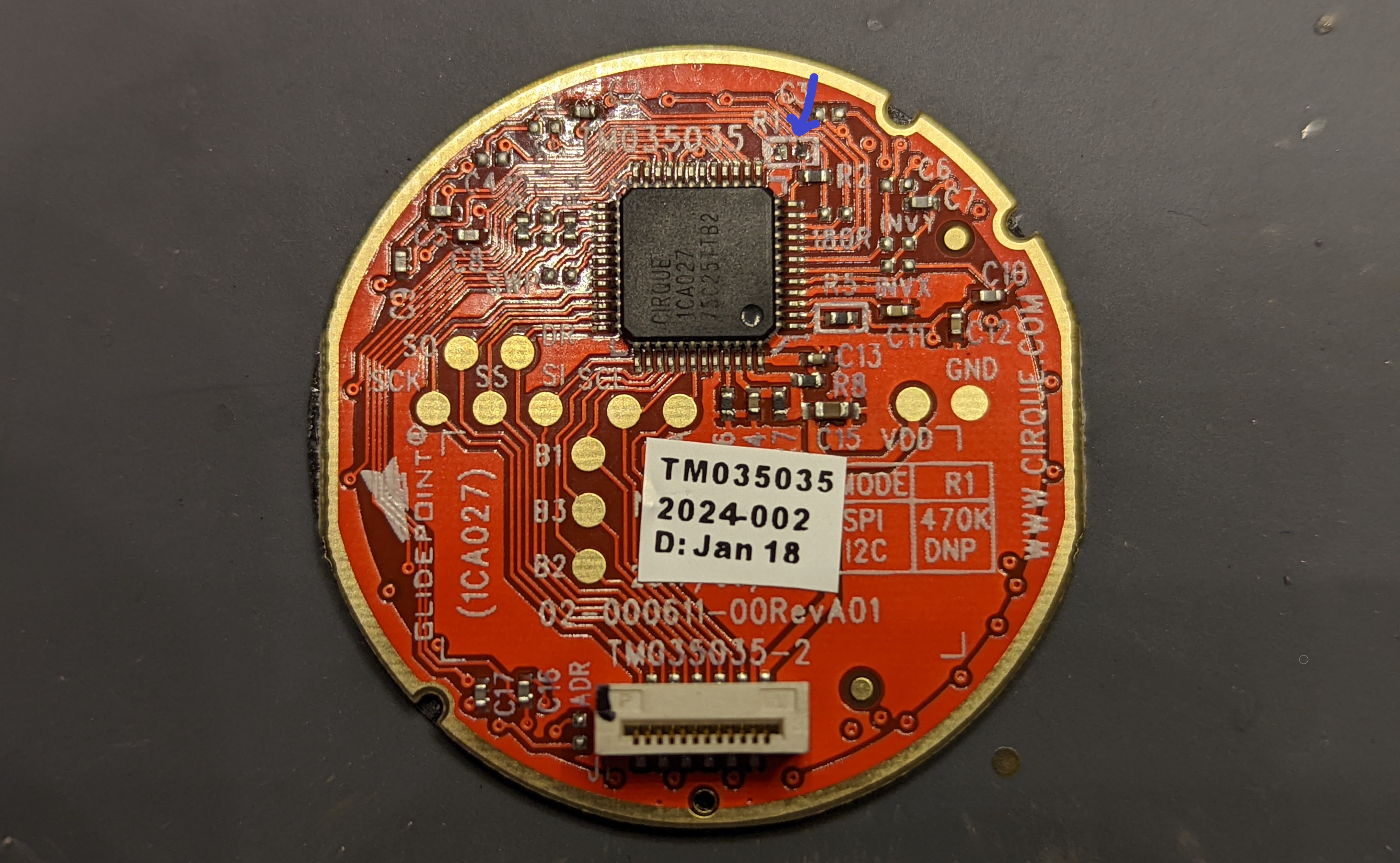
Remove the R1 resistor, indicated with the blue arrow, to enable the I2C protocol. Mine was already removed! Then, insert the trackpad into the case, such that the divots on the trackpad align with the protrusions on the case.
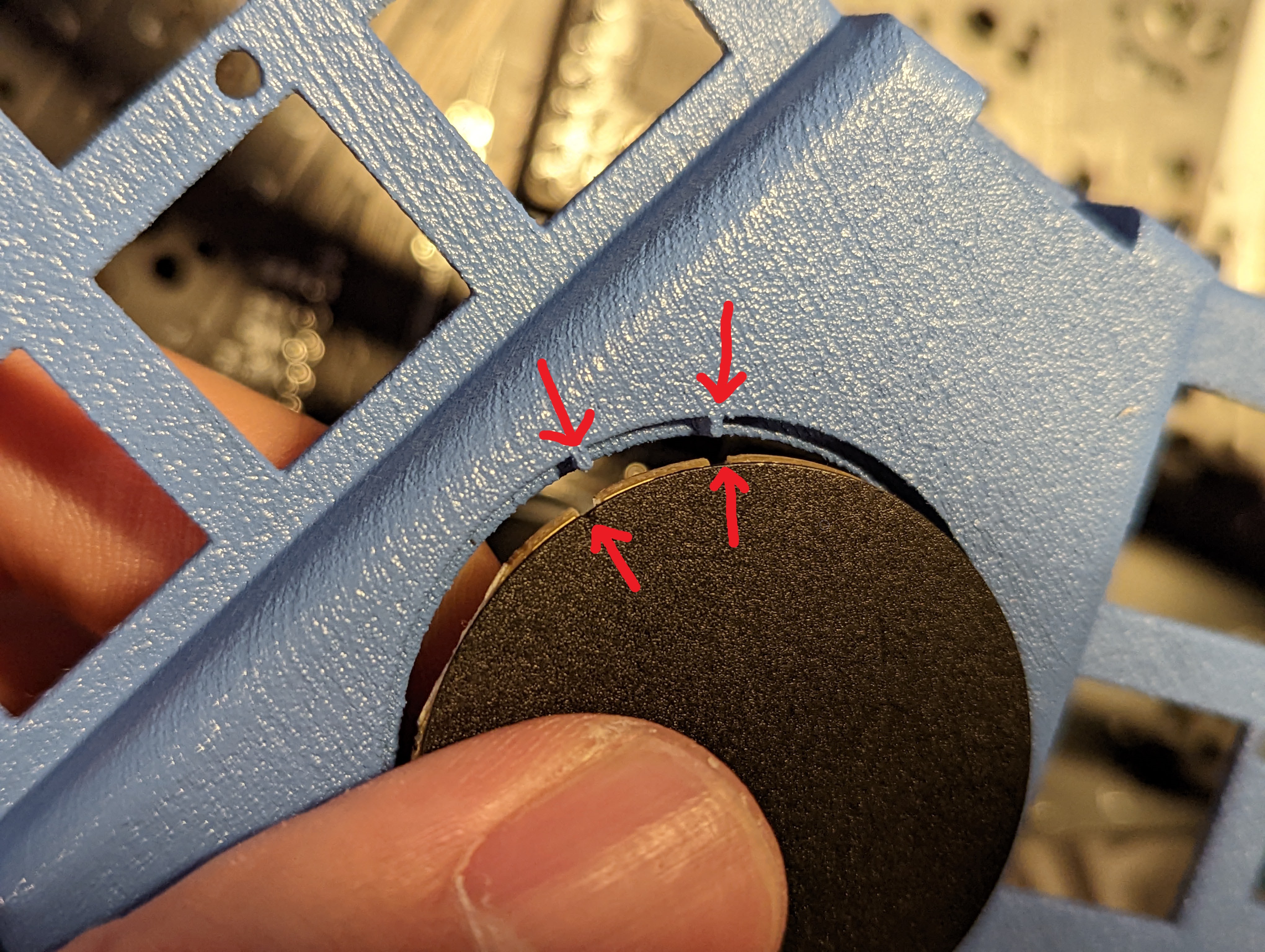
Align the trackpad to the case, via the markings indicated with the red arrows. After lining up the trackpad to the case, I use some hot glue to secure everything in place. I also connect the flat cable to the trackpad, such that the metal side of the cable contacts the metal parts of the trackpad socket.
We’re then going to thread the other end of the cable via the PCB’s ‘slot’ hole, from the top side of the PCB to the bottom side. The cable should then plug into the socket on the bottom of the PCB.
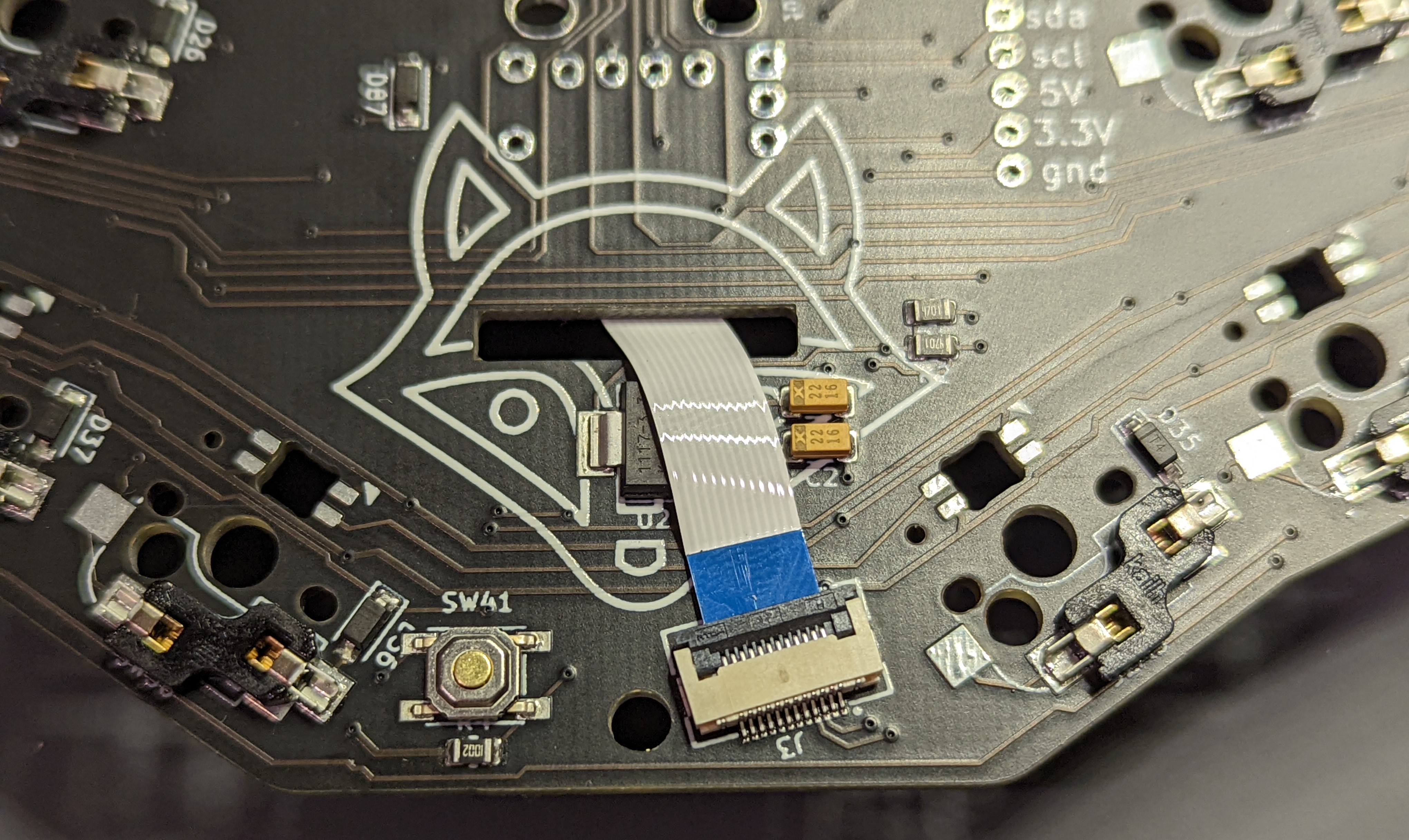
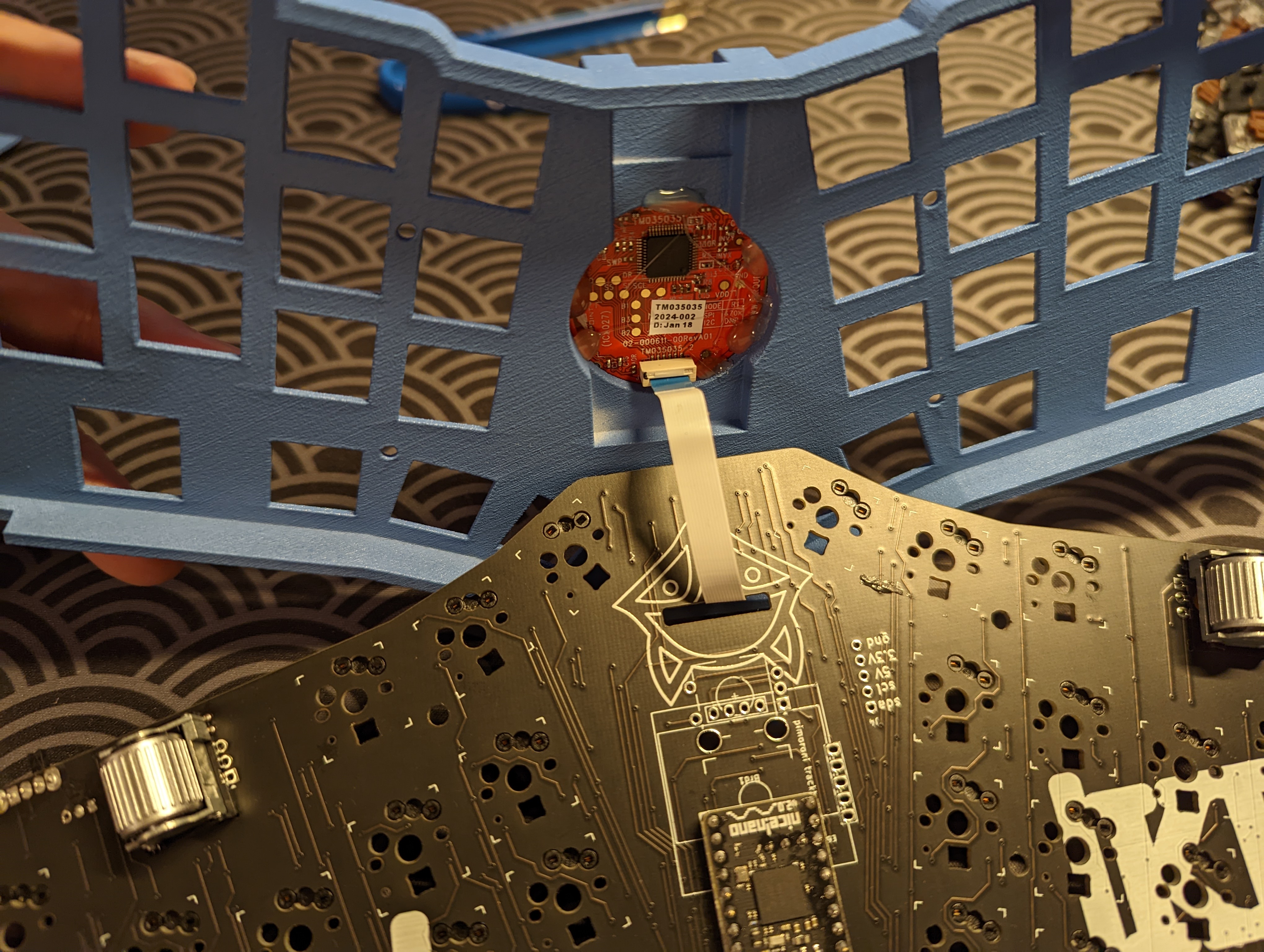
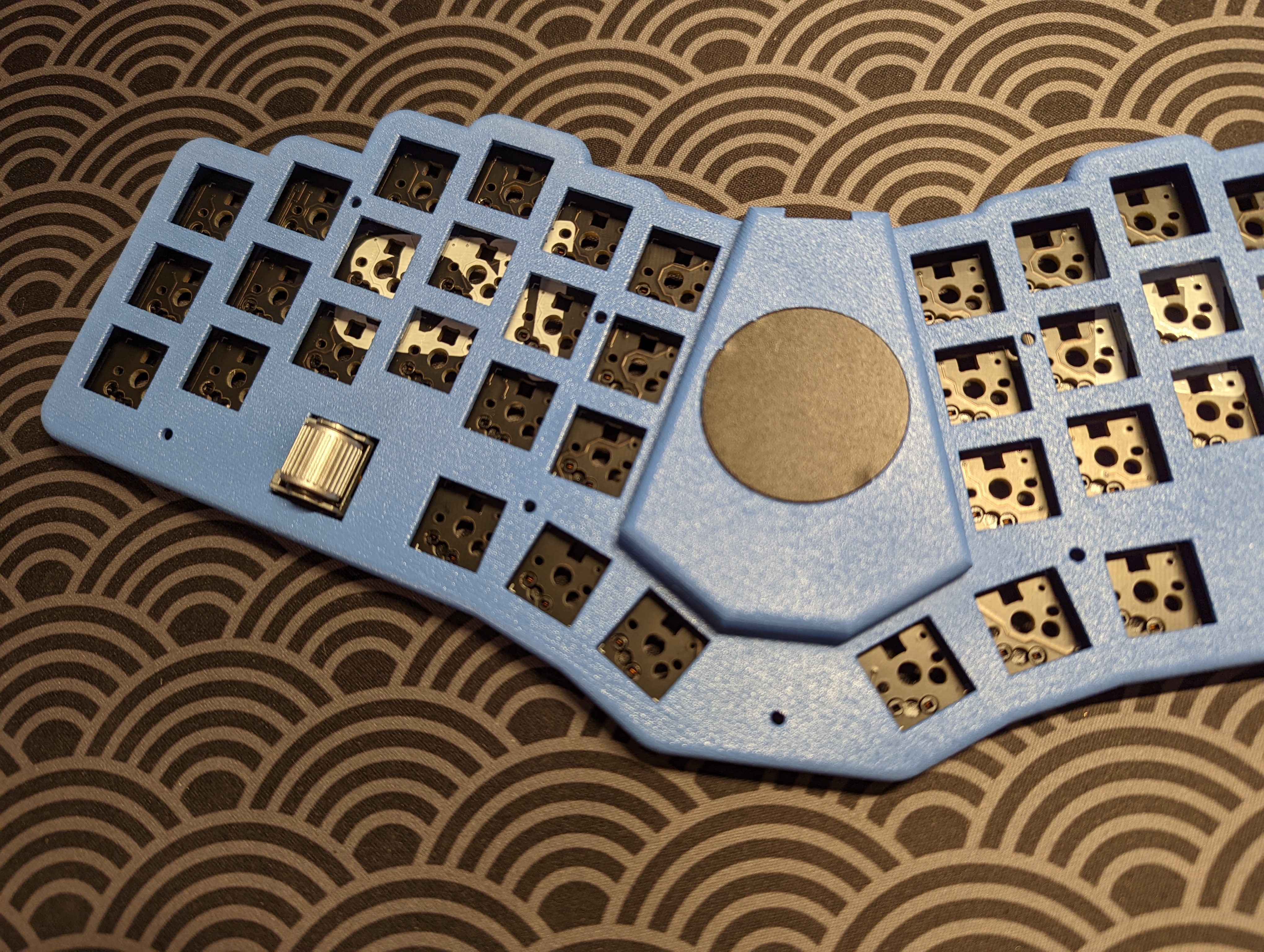
The first image shows the trackpad cable connected to the PCB socket. The second image shows the trackpad cable connected to the trackpad. Let’s just take a look at the trackpad with the top case, and admire our work so far!
-
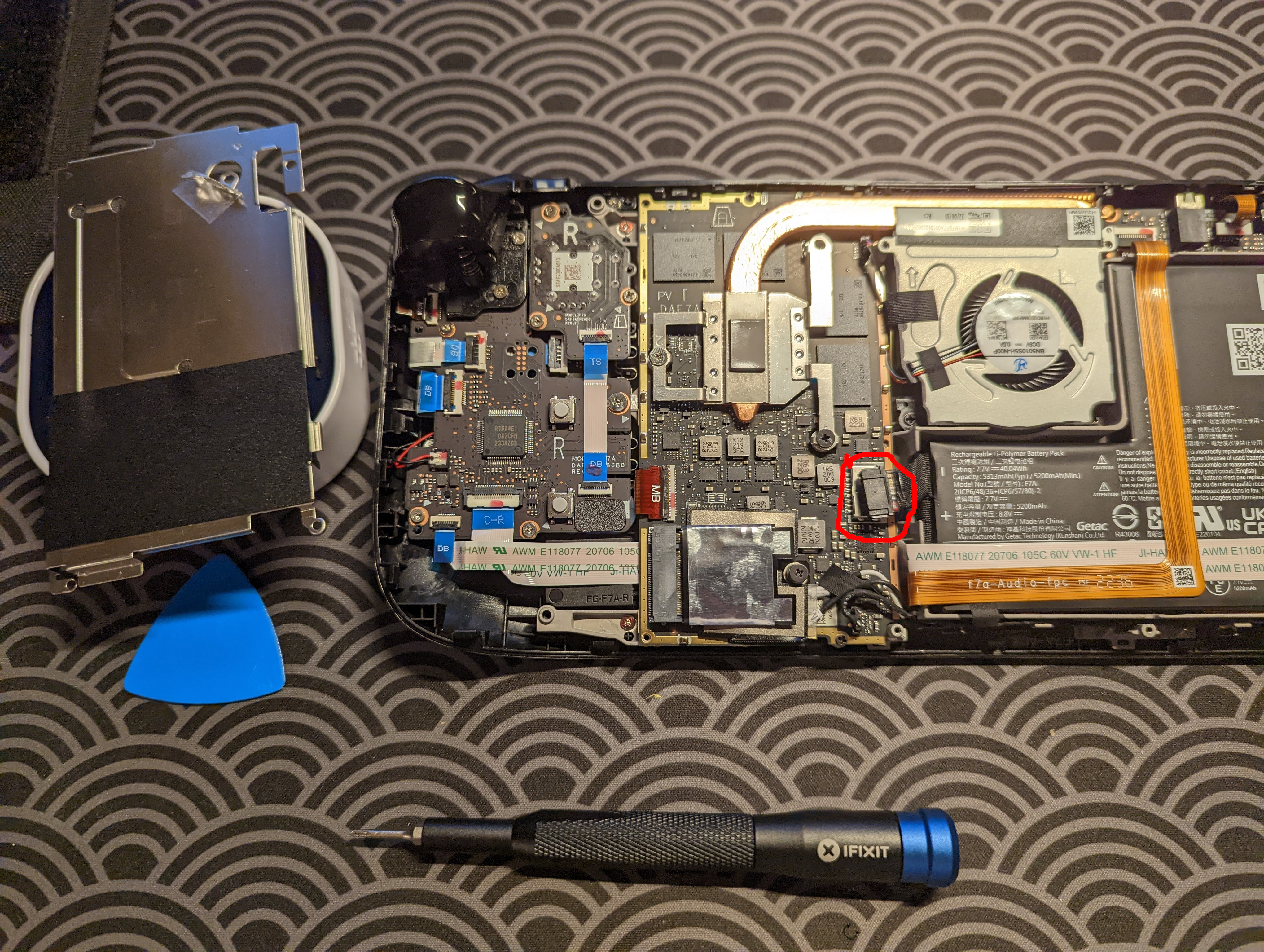
Connect the battery switch and JST socket. Connecting a battery switch and a JST socket is necessary, only if you’re doing a wireless build. I am, so I connected them! The Fingerpunch Discord server has a lot of great recommendations for doing alternative builds, and Sadek suggested a 2-pin JST connector and this toggle switch from Digikey, if building a wireless FFKB. The JST connector allows us to connect a LiPo battery in a reversible way, and the toggle switch lets us cut the battery’s connection to the keyboard, so we conserve on battery life. The JST connector is a 2-pin, even though the keyboard PCB has 3 pins for the battery’s JST—the reasoning is that if a battery already has a JST header crimped on, the VCC and GND cables may be fixed in one orientation or another, and may require the user to flip the battery’s polarity, which can be annoying.
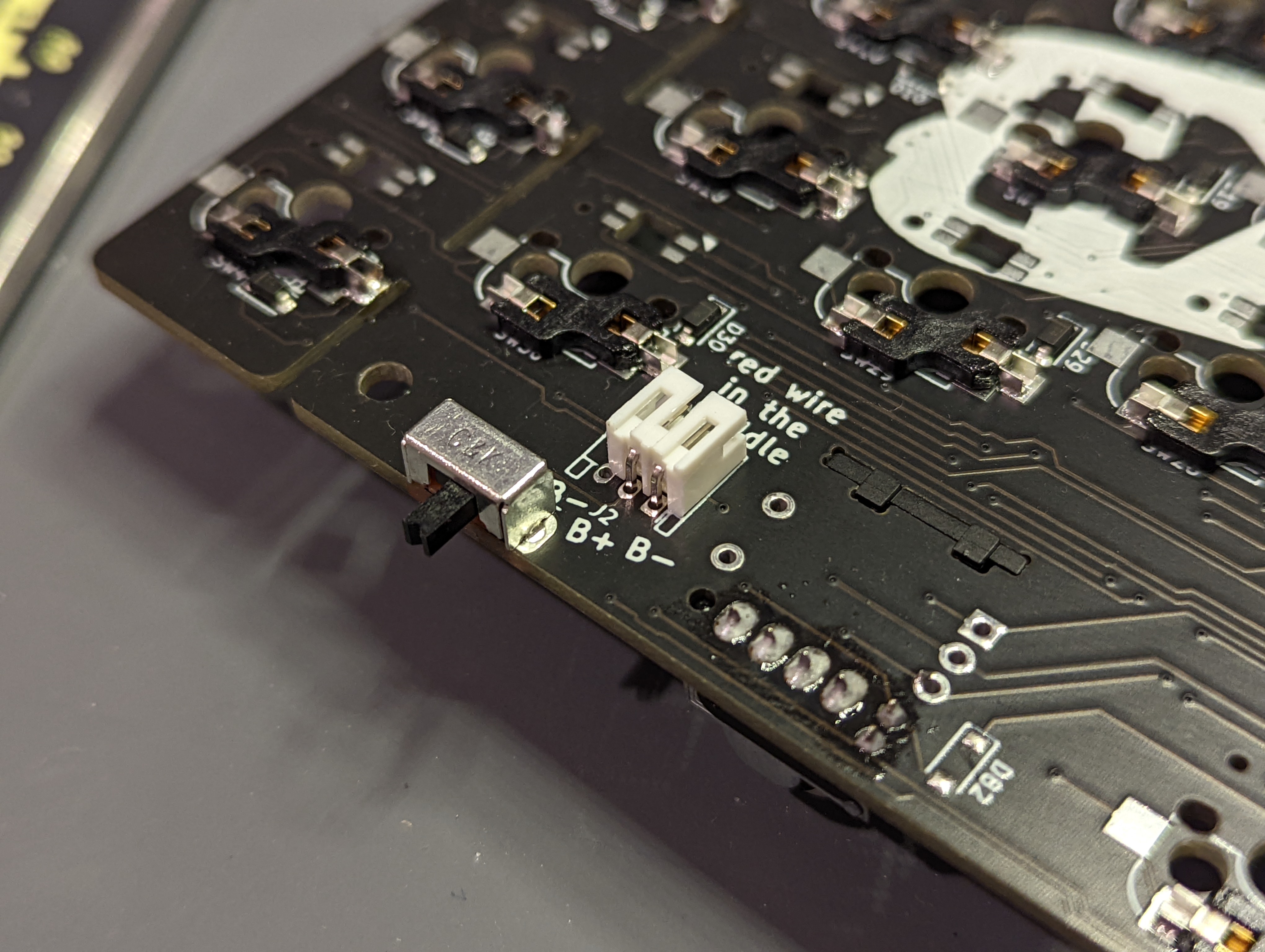
The battery power switch and the battery JST connector on the PCB. Note tha the PCB’s silkscreen says ‘red wire in the middle’. It refers to the VCC wire of the LiPo battery. -
Connect the battery. I found a really cool 400 mAH battery on AliExpress that’s only 3 mm in thickness. I extended the battery wires and crimped JST connectors onto the battery leads.
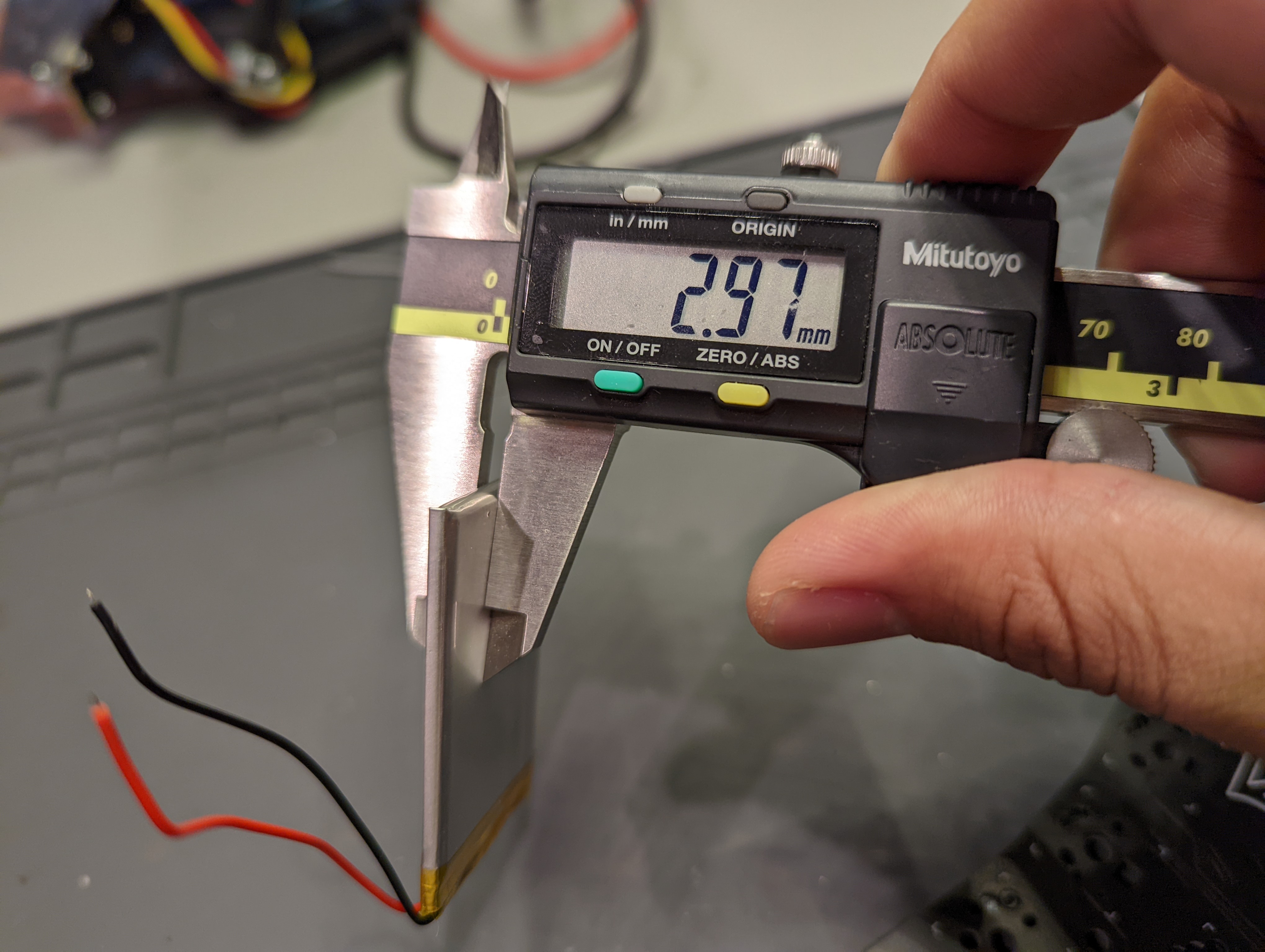
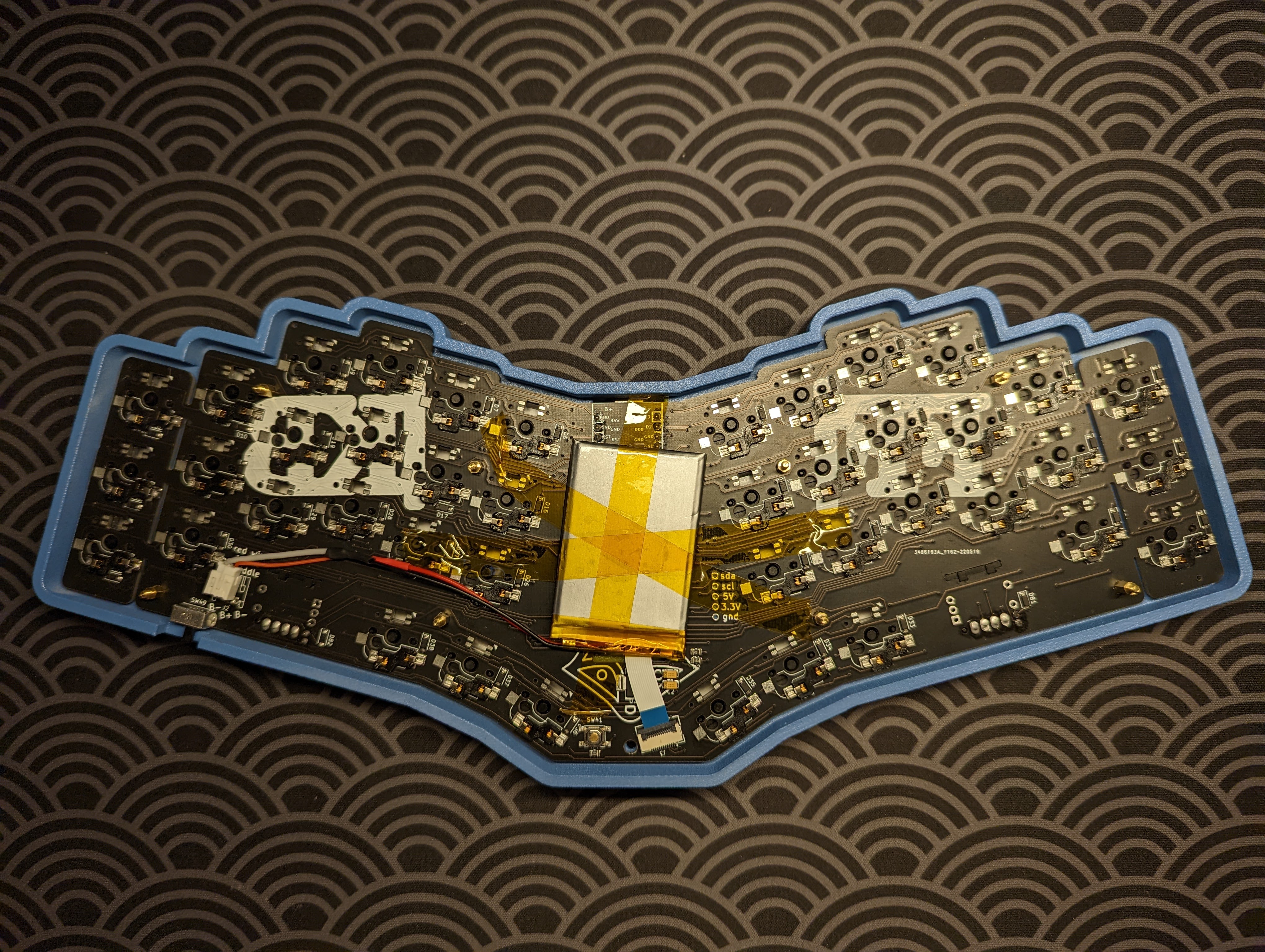
Look at how thin the battery is! It sits even lower than the edges of the top case! I secured the battery to the PCB with some Kapton tape, like a professional. I’m really pleased with the dimensions of the battery. The battery’s length and width are small enough that it doesn’t interfere with the hot swap sockets, and it’s also super thin.
-
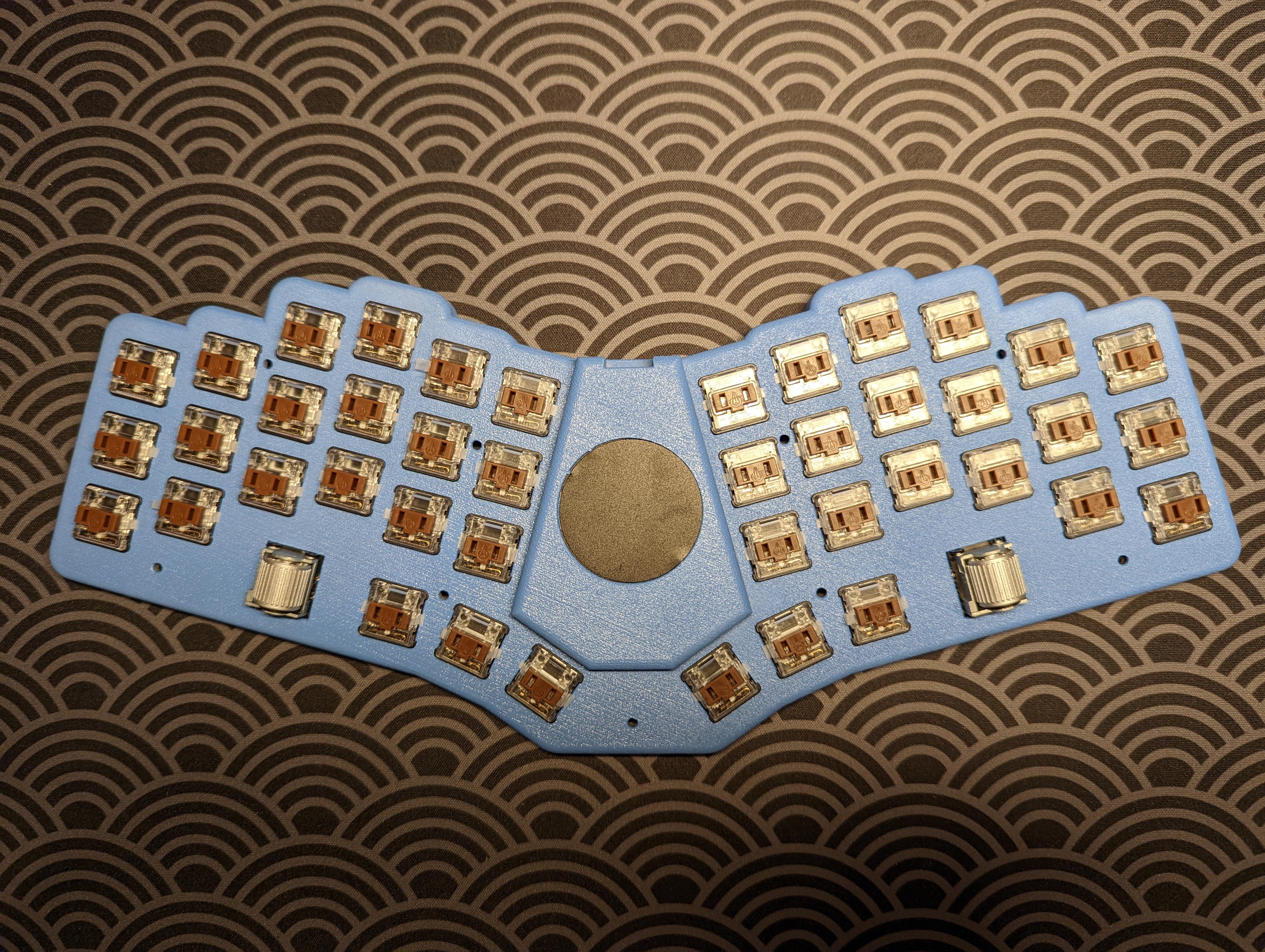
Add the switches. It’s time to add the switches! I’m using Brown Kailh Low Pro Choc switches (60 g, tactile). The official docs say that it’s better to add the switches on the outside columns, first, but I found that it didn’t matter too much. Maybe Sadek revised the board for the later batches.
Case and Keycaps
At this point, we’re finished all the electronics. We just need to finish assembling the case together. We add 8 (or optionally, 9) M2 x 8 mm F-F hex standoffs to the allocated holes in the PCB. These holes should align with holes that are present on both the top and bottom case parts.
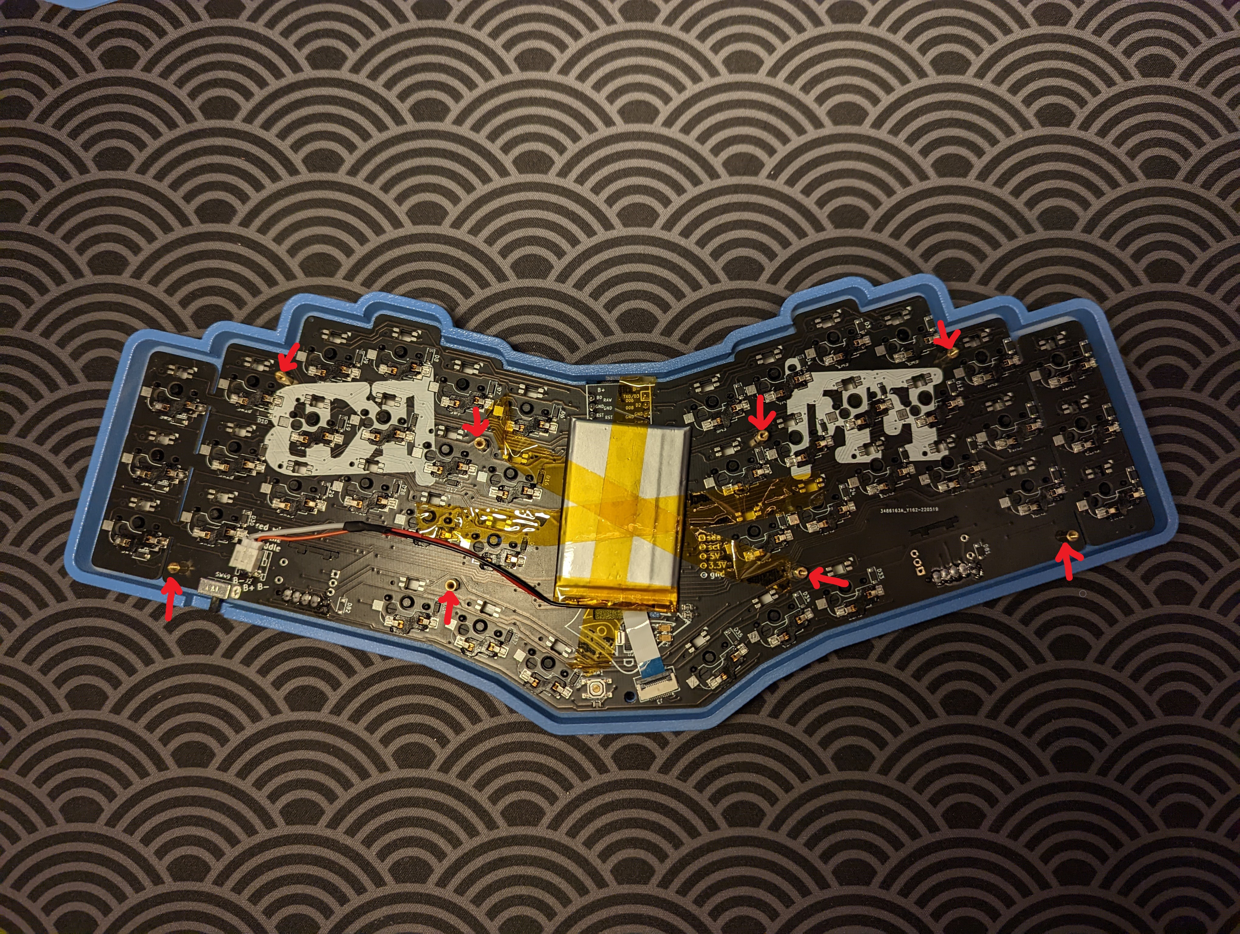
Then, we line up the bottom case part, and secure everything into the bottom case with M2 screws (the length doesn’t really matter, so long as they’re just long enough to reach the threads of the standoffs. In general, try to use the shortest screws you can get away with). We also apply some bumper stickers.
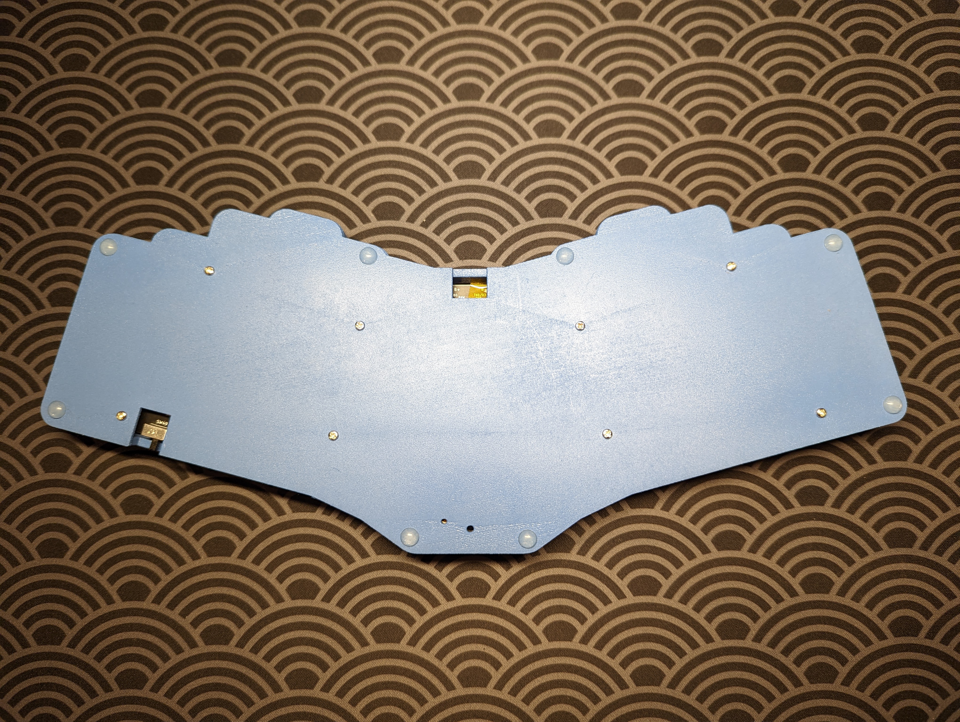
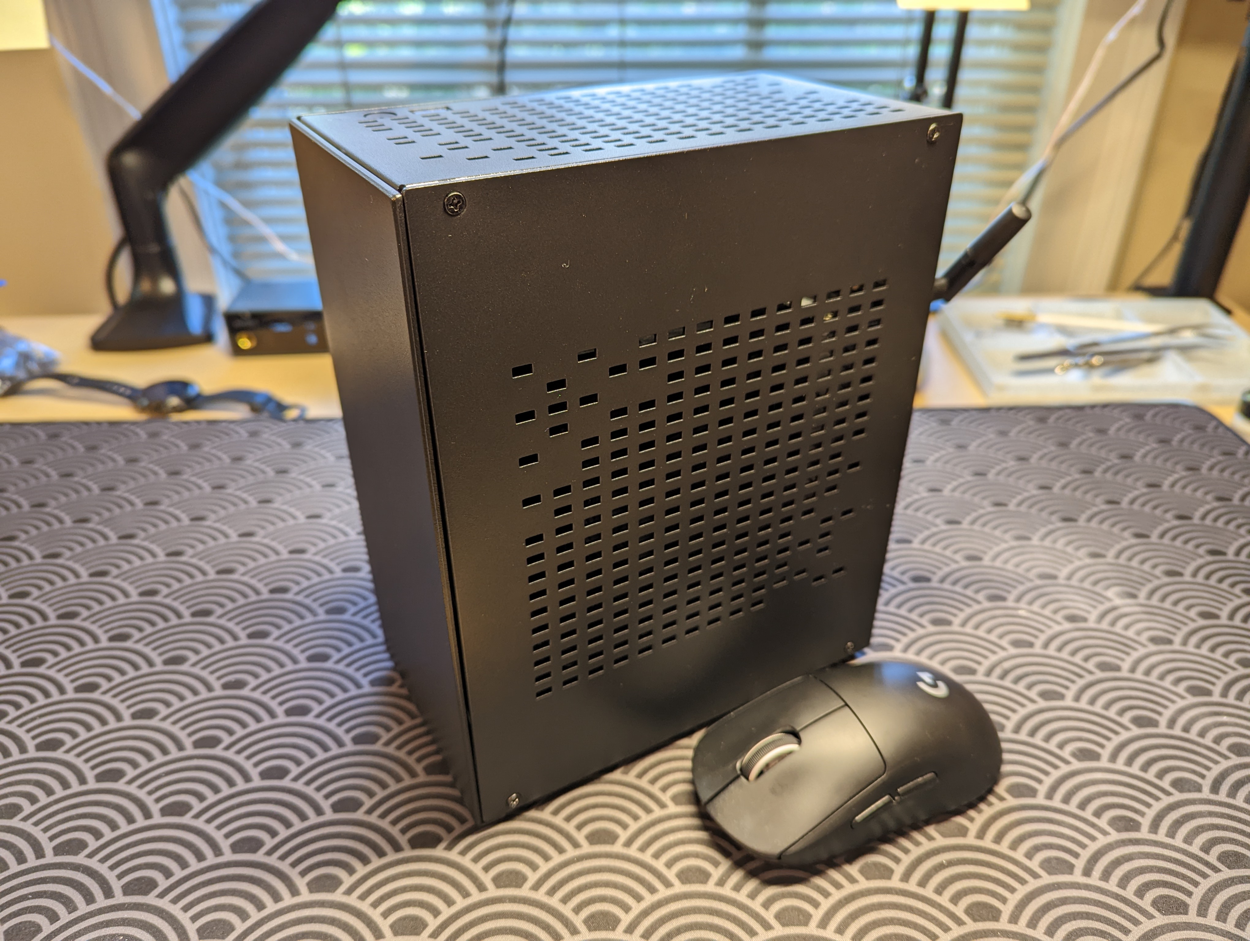
Finally, we flip the keyboard over, and screw in M2 screws into the hex standoffs from the top side, so that the top case is properly secured. We also pop in the keycaps. I’m using some white MBK Legends.

Awesome! The hardware is all done ![]() !
!
Firmware
Next, we’re going to upload some firmware! Admittedly, I should have thought about the firmware more ahead of time. I’m using a Nice!Nano (v2) µC, which at least for now (as of 2022/09/27) requires that I use ZMK as the code base for generating the firmware. In some sense that’s great, because ZMK’s support for wireless keyboard builds is unmatched. The drawback, however, is that ZMK does not yet support pointing devices like the Cirque trackpad, which I have installed on my FFKB! So, my wireless trackpad FFKB build has incredible wireless support, but its trackpad is currently just an art piece ![]() . An alternate and OG codebase for generating keyboard firmware, QMK, definitely supports pointing devices, like the Cirque trackpad, but it doesn’t support the Nice!Nano µC …. Apparently, some talented people are working on implementing pointing devices (and specifically, the Cirque) into ZMK, so it sounds like I can just wait, and eventually all my desired functions will be integrated into ZMK and by extension, my FFKB.
. An alternate and OG codebase for generating keyboard firmware, QMK, definitely supports pointing devices, like the Cirque trackpad, but it doesn’t support the Nice!Nano µC …. Apparently, some talented people are working on implementing pointing devices (and specifically, the Cirque) into ZMK, so it sounds like I can just wait, and eventually all my desired functions will be integrated into ZMK and by extension, my FFKB.
Something worth noting for folks is that Sadek likes to keep his GitHub code separate from main repos, like the main QMK and ZMK repos. Fortunately, using Sadek’s ZMK code is very straightforward! We first fork Sadek’s zmk-ffkb repo. Then, we make changes to the local keymap file, as desired. Then, we go to the webpage where our fork is, and make sure that GitHub Actions is enabled (I think you just need to click a green “accept” button on the webpage). At this point, everything’s the same as a regular ZMK configuration. We add, commit, and push our changes, then navigate to the GitHub Actions tab, and download the generated firmware.zip artifact. We extract the firmware.zip, put our keyboard into bootloader mode via double-clicking the reset button on the back of the keyboard (which tricks the computer into thinking the keyboard is a sort of mass storage device), and drag the .UF2 file into the keyboard / Nice!Nano ‘mass storage device’. If there are ever any questions, I can highly recommend the Fingerpunch Discord server. It’s a super helpful and responsive community!
Footnotes
-
Spoiler, I did not find a non-row-staggered monoblock keyboard that is also tented. I guess it’s kind of a niche build, because the sort of person who would desire a tented keyboard, is the sort of person who is hyper ergonomics-oriented … and so they would insist on not only a tented keyboard, but also a true split keyboard. There are a lot of tented keyboards out there, but not too many tented monoblock keyboards. Maybe I’ll design and make one. ↩