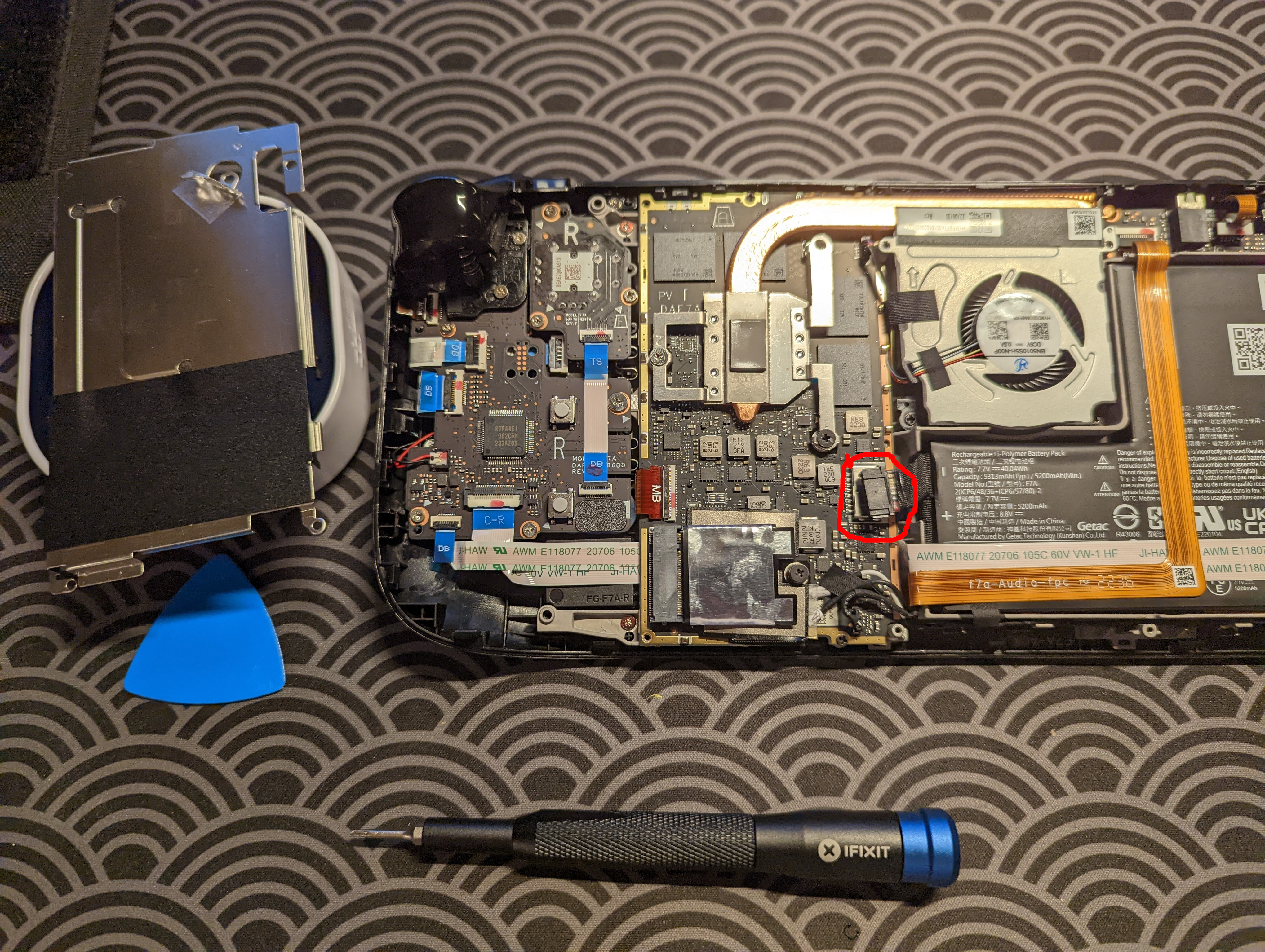
I’ve been using the power strip under my desk for a number of years. One of its convenient features is that it has four USB ports, so you can charge your USB devices directly into the power strip. I noticed the other day that the USB ports fell deep into the cavity of the power strip, which prevented my USB cables from being able to reach the charging ports. The issue was clearly a mechanical one, rather than an electrical one. So, the fix should be fairly easy. I briefly document the fix here.
First, I disassembled the case. I just had to unscrew some triangle screws in the back, to access the electronics.
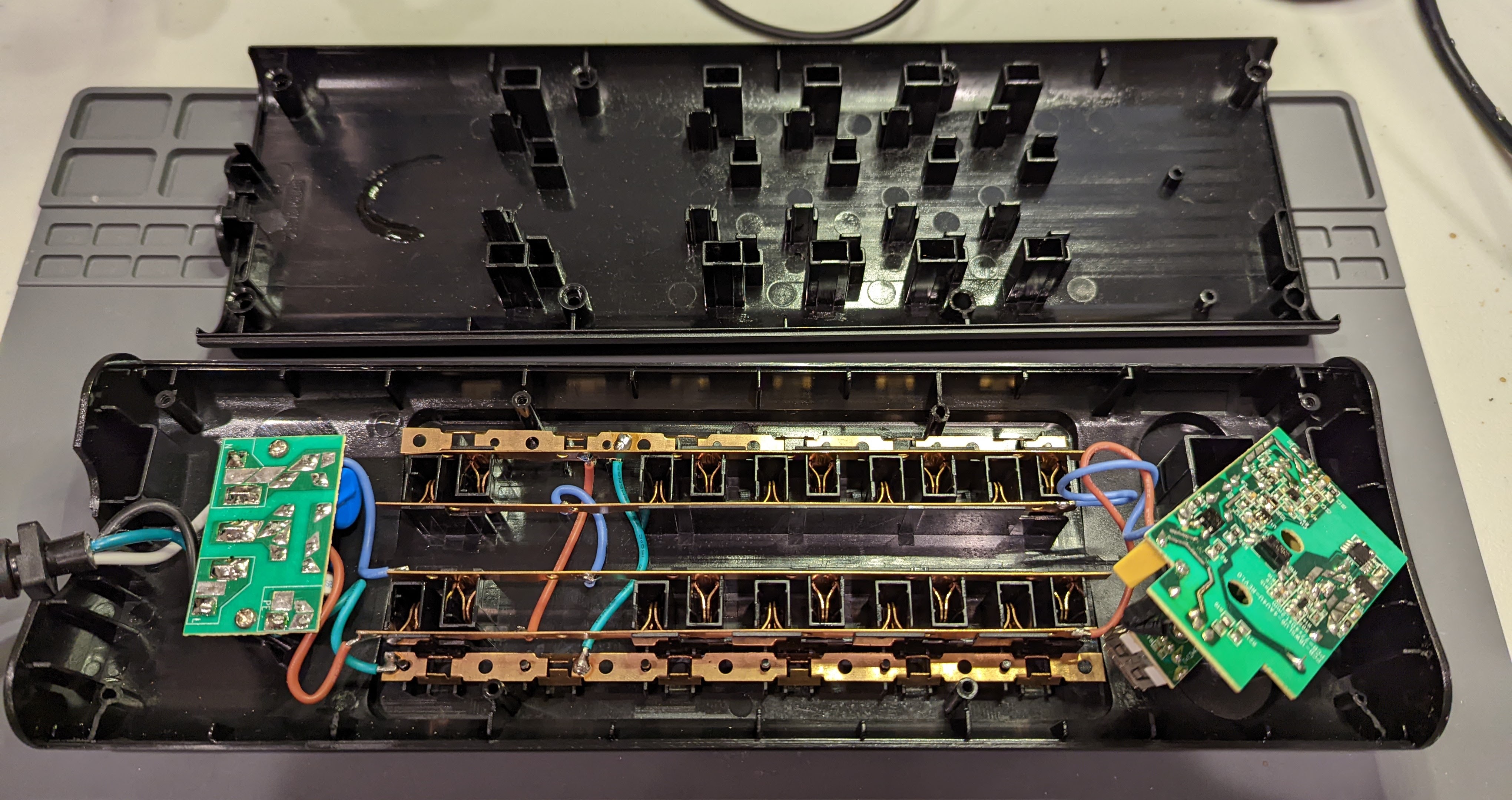
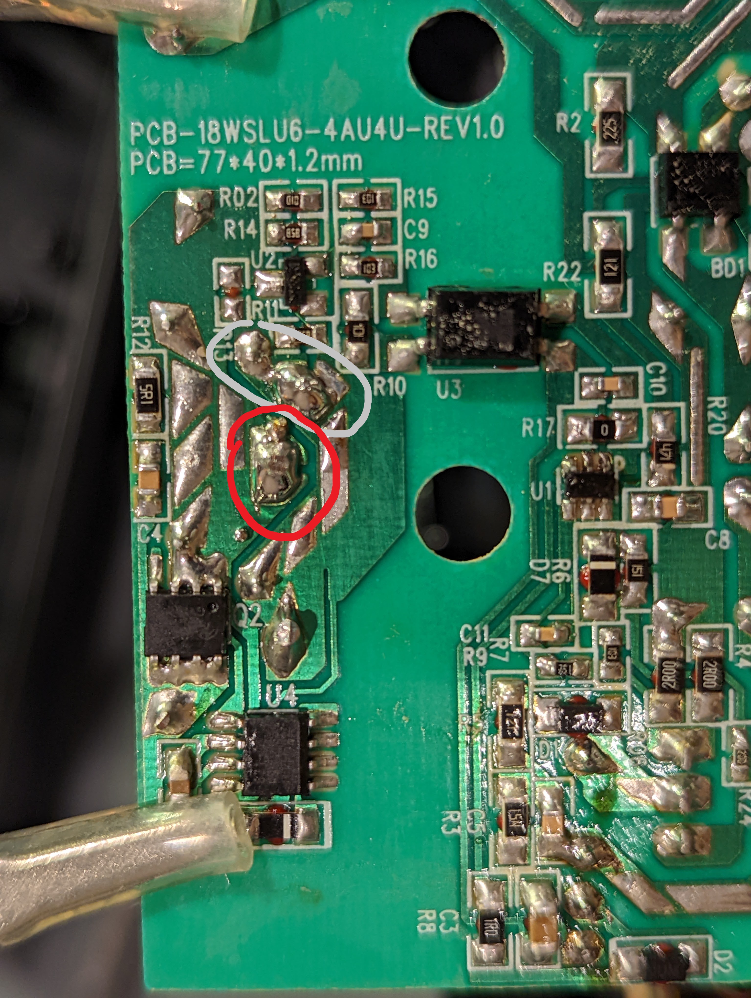
The cause of my issue was easy to see. The stand-offs that secured the USB ports’ PCB to the case were broken. There was no way I could directly fix those stand-offs, so I figured that I could maybe chaotically hot glue everything into place. Most importantly, I’d need to access the PCB that the USB ports were on, and I’d have to glue that board back into place. Doing so would require me to desolder the V+ and GND wires that were entering the USB board. Even though V+ and GND are only two wires, I felt like I could not throw the fate of my power strip into my faulty working memory. So I took a photo that I could use as reference for when I’d have to solder the wires back in place.
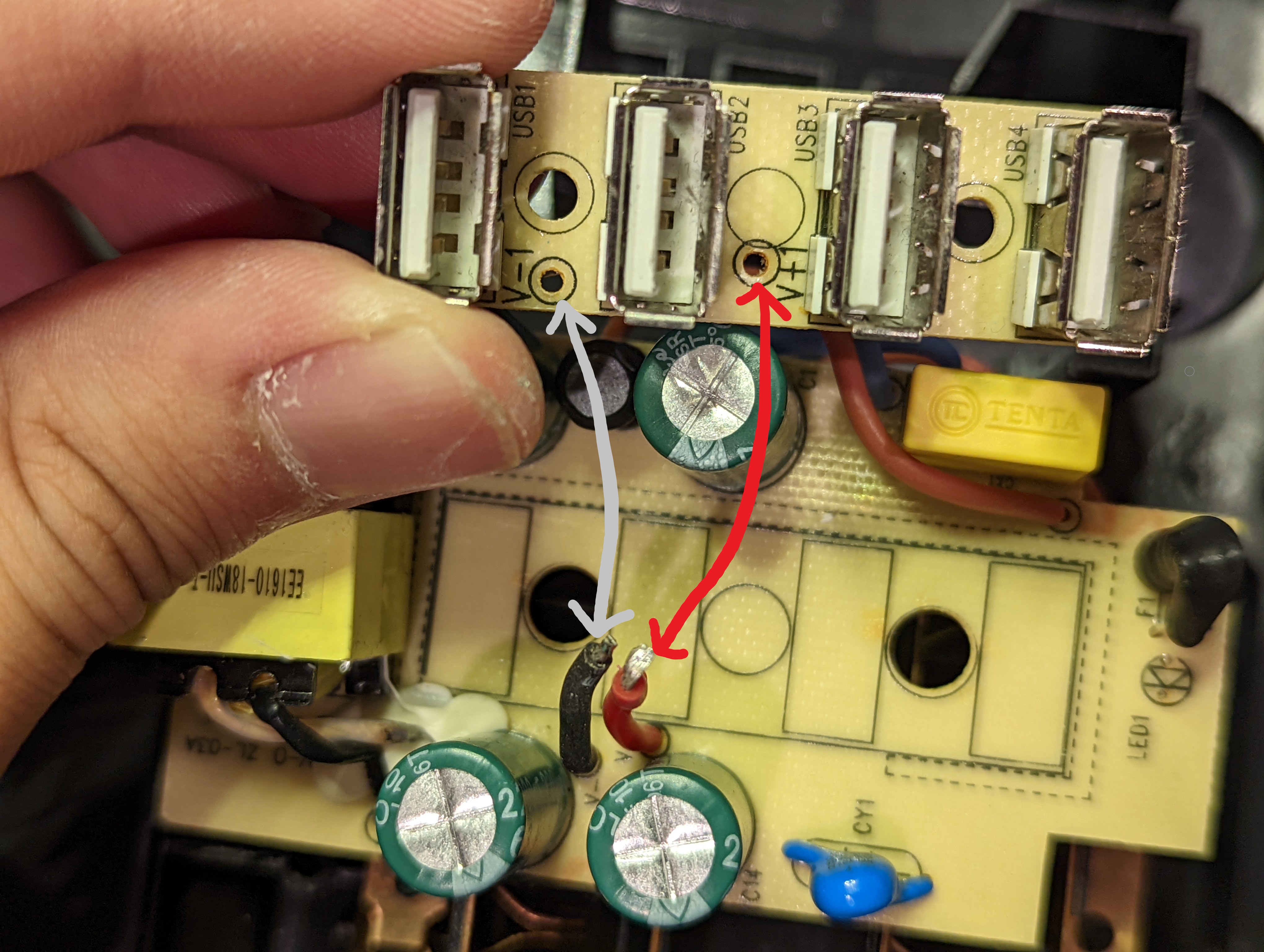
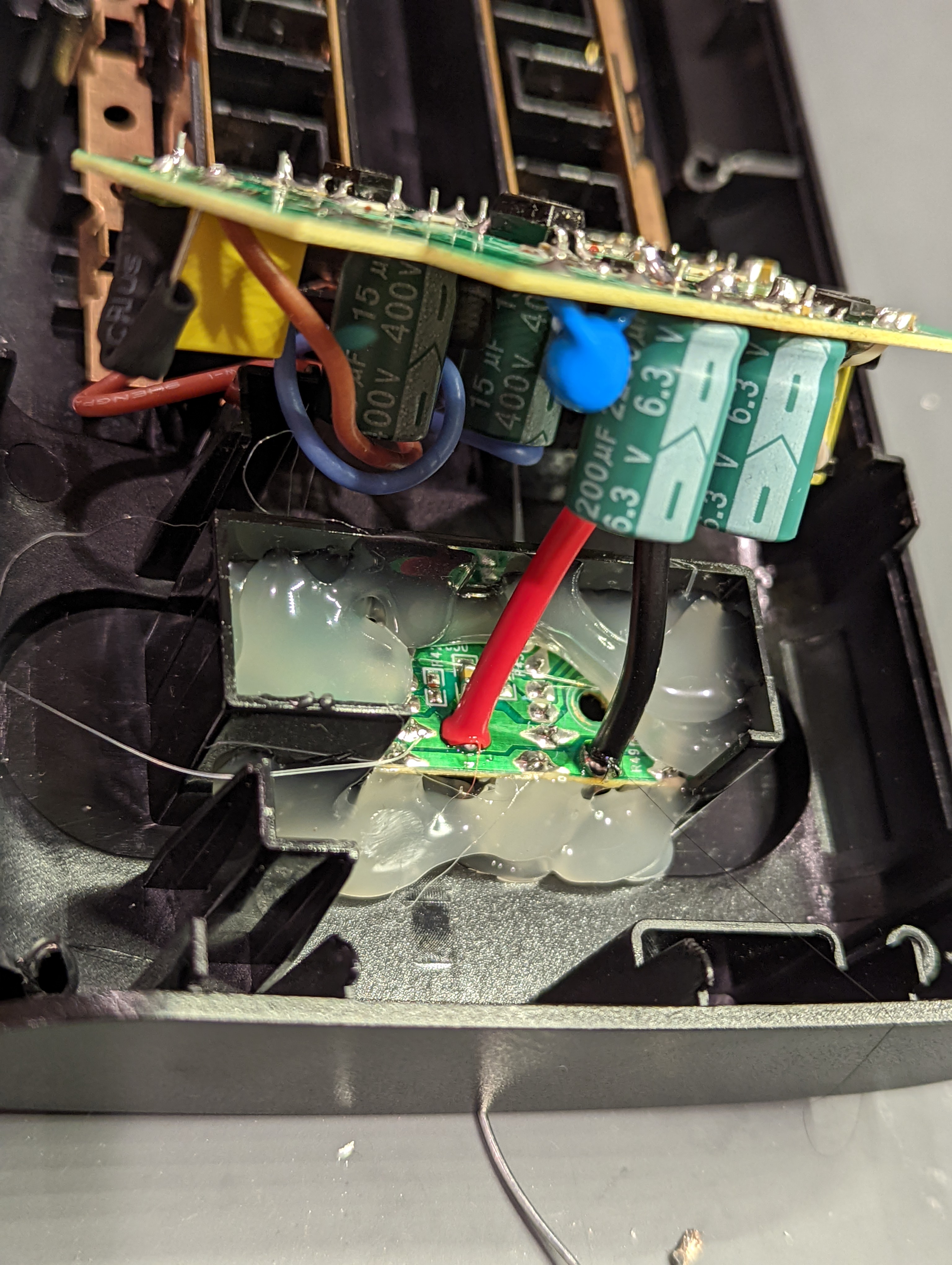
Very simple! Time to throw on hot glue, one of the humankind’s greatest inventions.
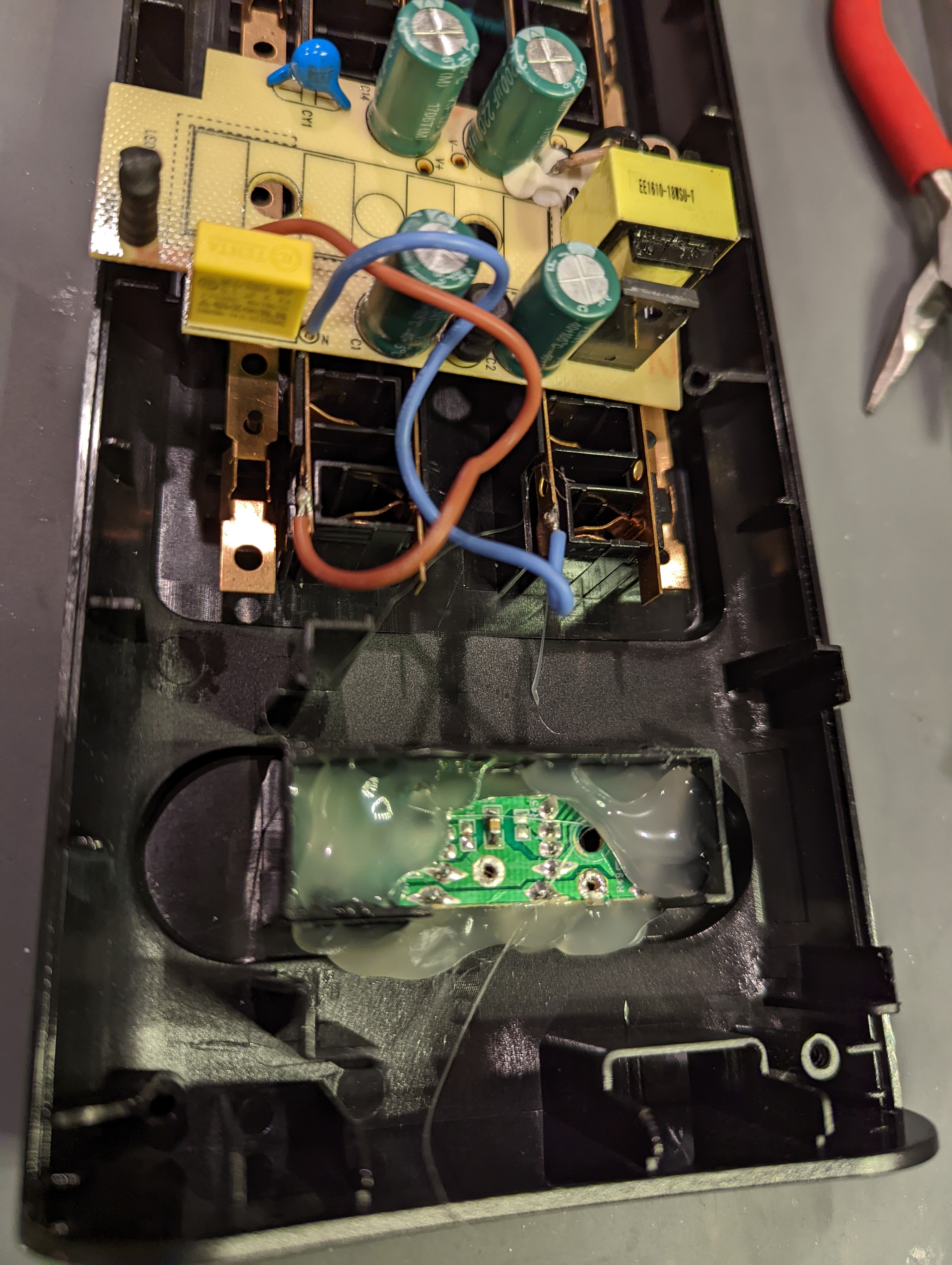
I then realized that the short lengths of the red V+ and black GND wires made soldering the USB PCB back onto the main PCB somewhat impossible. So I desoldered off the wires from all their connections. I took note of the fact that the solder joint on the GND cable was shared with some other stuff. I made sure to take a photo, because I found this shared joint a little weird, and I could see myself second-doubing its existence upon resoldering1.
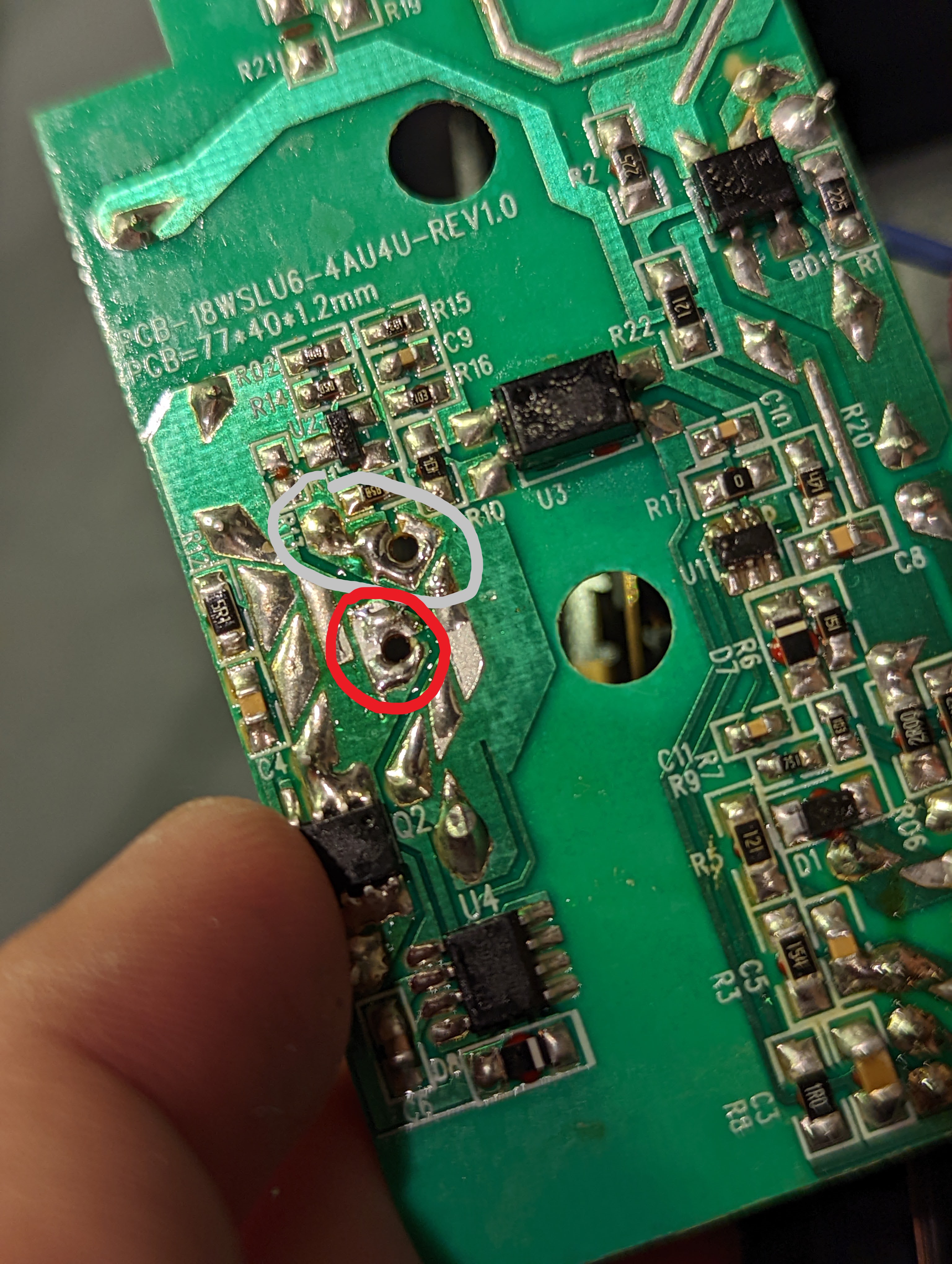
Upon successful desoldering, I went HAM on the hot glue, again. Then, I soldered the wires back to the main PCB.
At this point, I screwed the case back up. At best, my peripherals will successfully recharge. At worst, my peripherals will blow up. Or on a less dramatic note, my peripherals just won’t charge. Moment of truth …
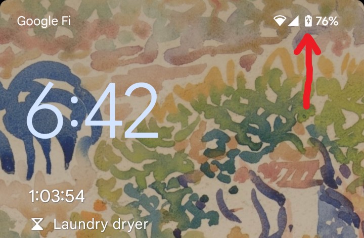
Hooray, disaster averted! Funny how stressful soldering two wires can be ![]() .
.
Footnotes
-
I guess the shared joint makes electrical sense though, because it’s just a common GND. I just haven’t seen common GNDs routed in this way before. ↩