The place I’m living in is very old, and has some antiquated housing features. Notably, the hot and cold faucets of my washroom are separated, so achieving a comfortable water temperature is near impossible.
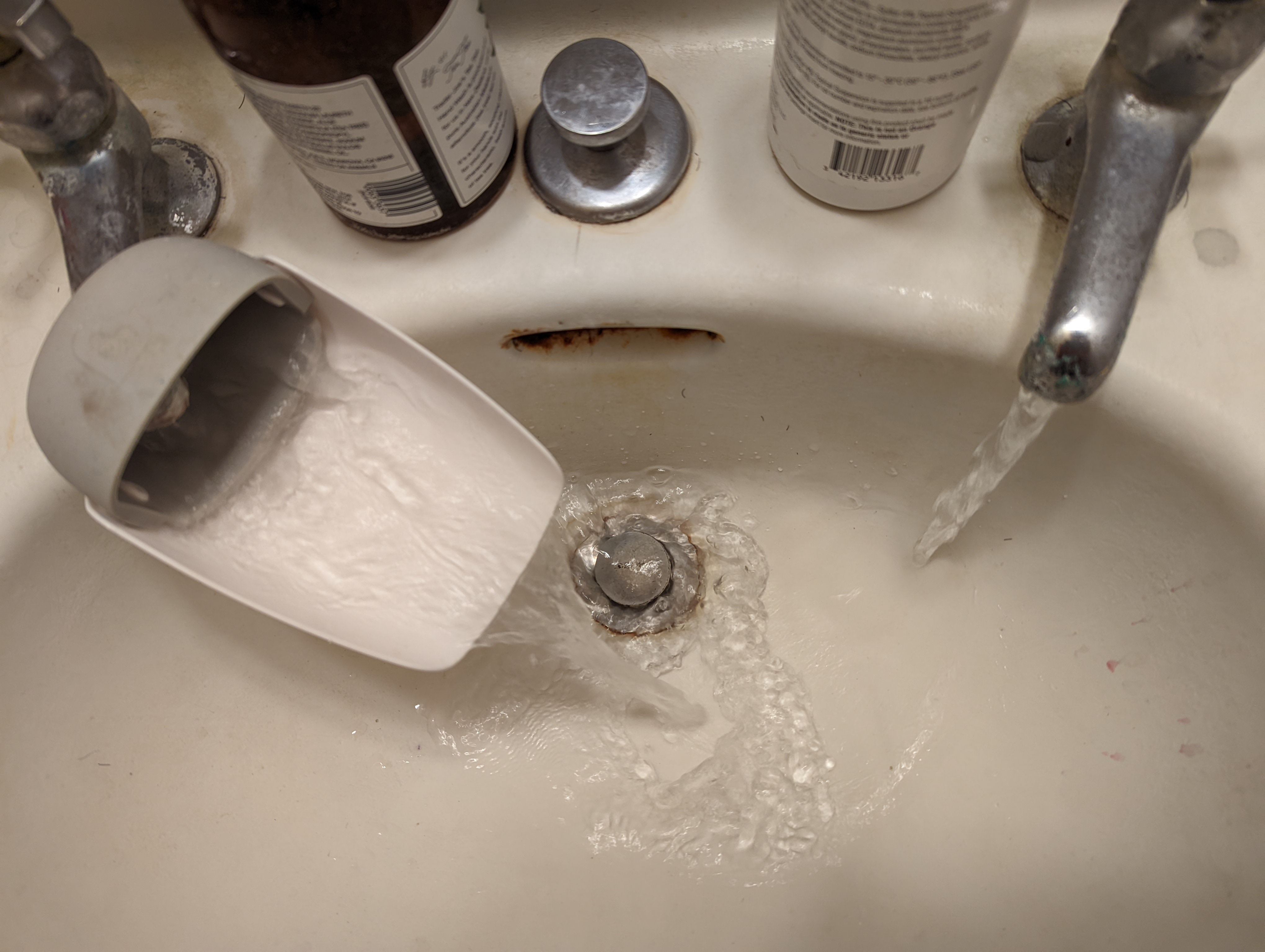
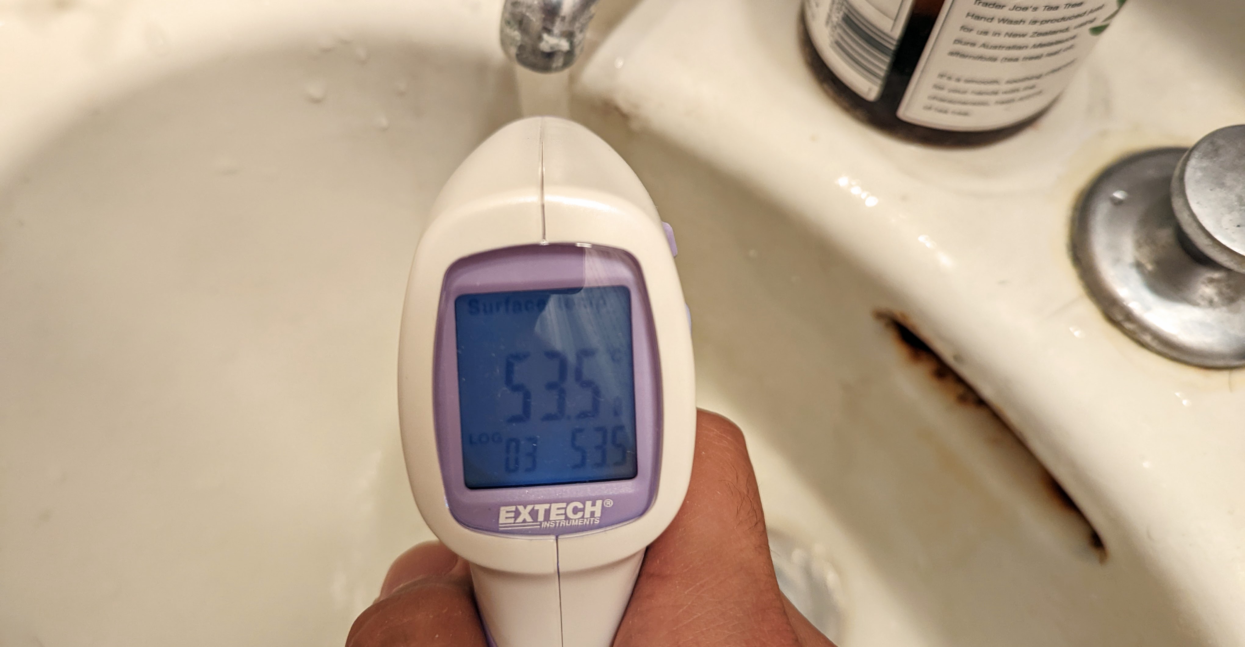
For a while, implementing an extender on the hot water faucet was a sufficient solution, because the hot water used to be very tame. I could crank up the hot water faucet as much I wanted, and the resulting water temperature would reach a comfortable warmth. Recently, however, a building-wide plumbing ‘repair’ overcorrected the faucet’s hot water temperature. Now, even a small adjustment of the handle results in a skyrocketing water temperature increase.
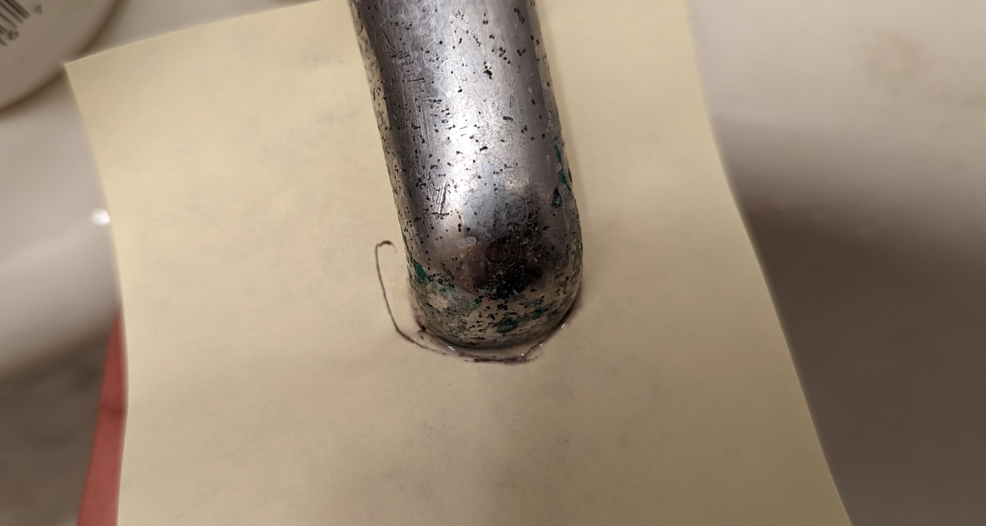
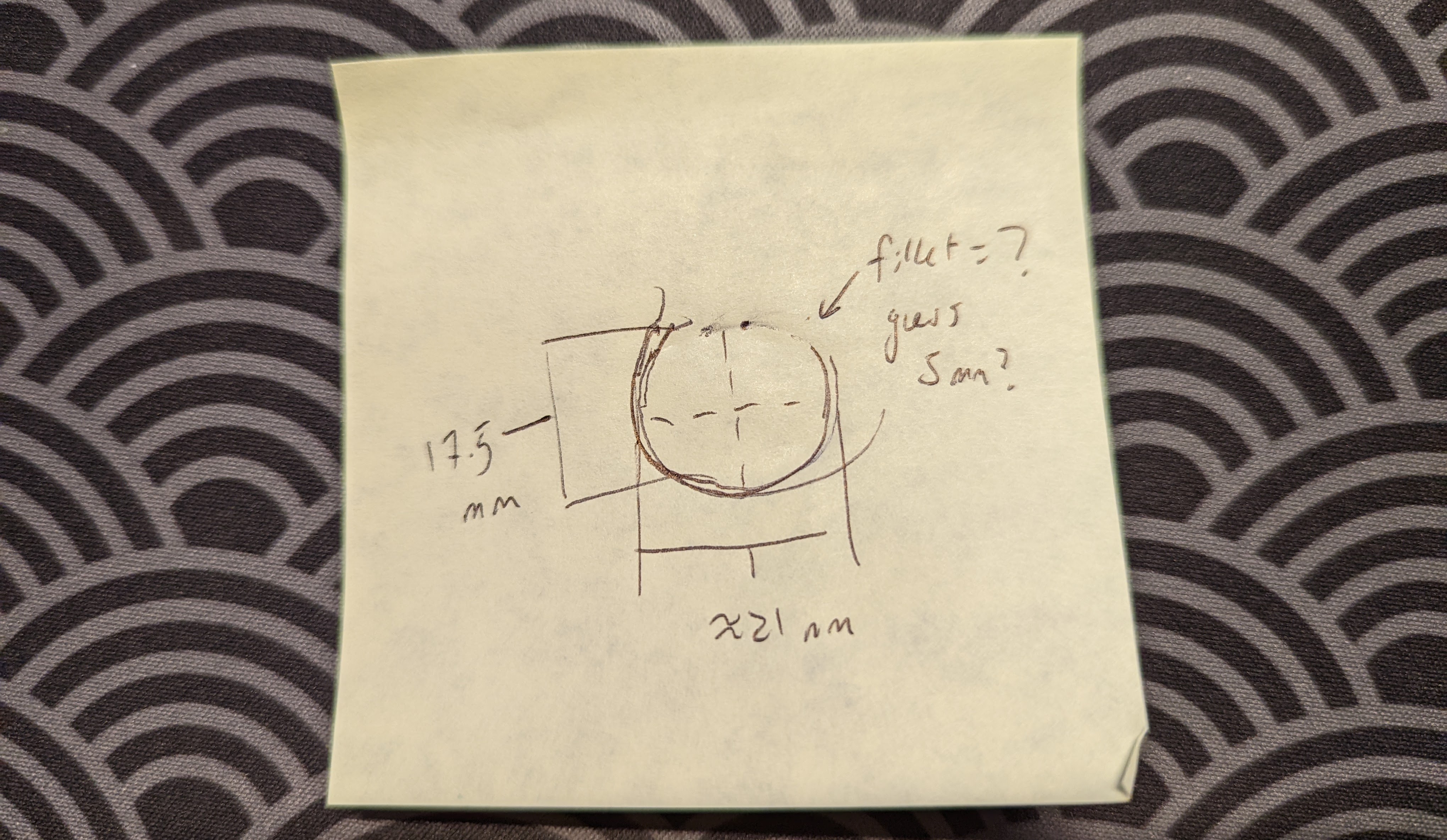
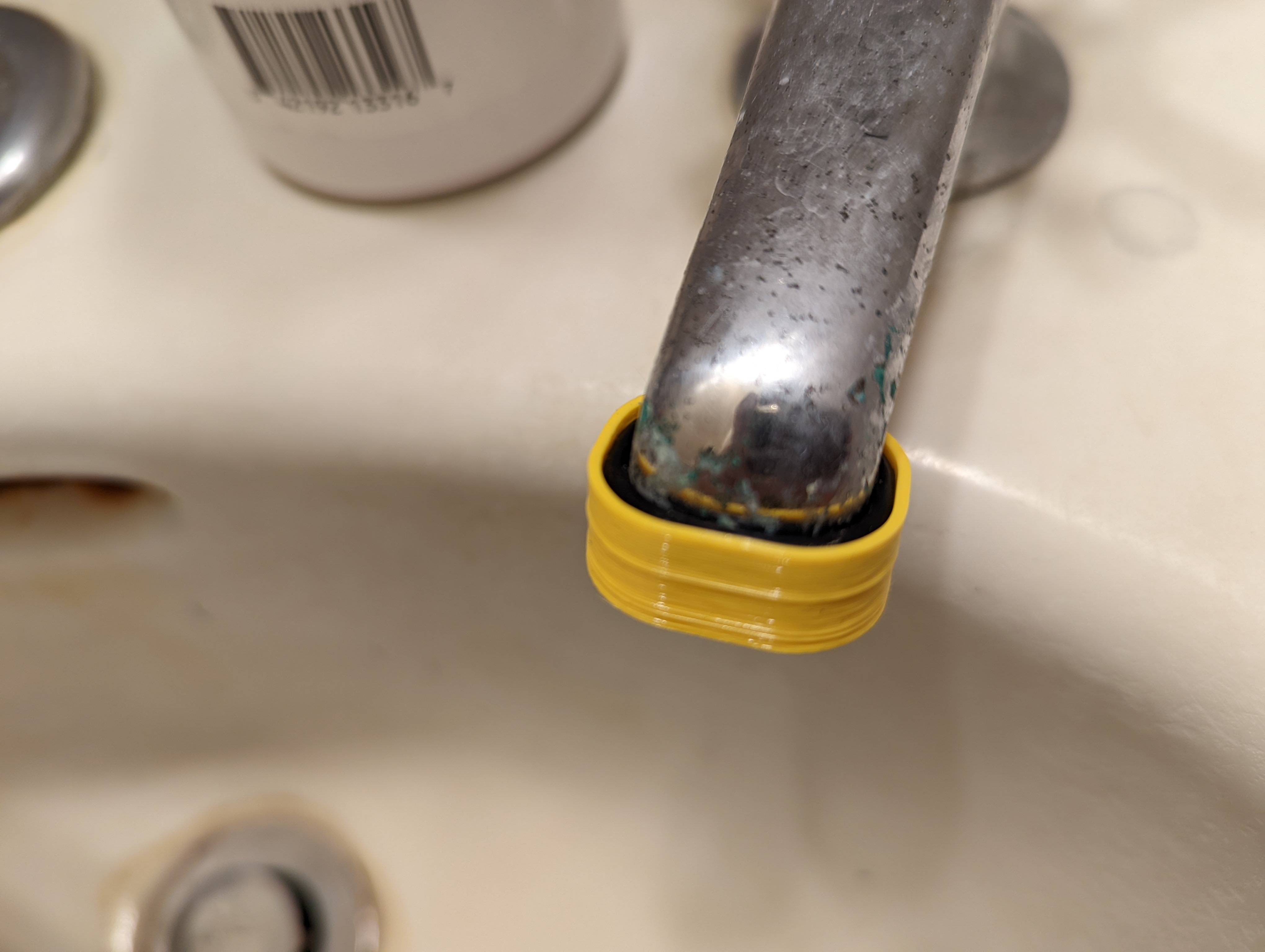
I thought that designing and building a 3D-printed solution would be both fun and useful. I began by estimating the faucet dimensions.
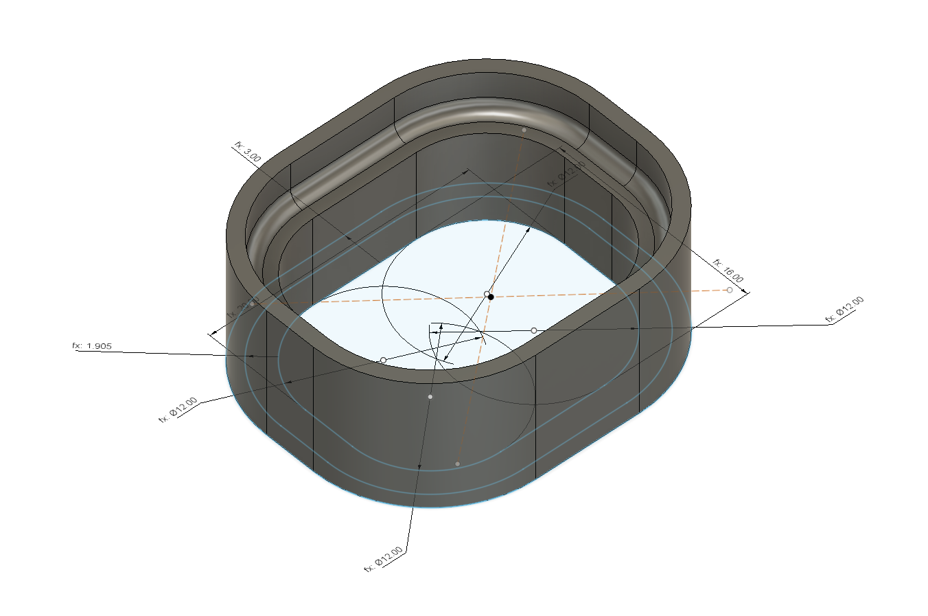
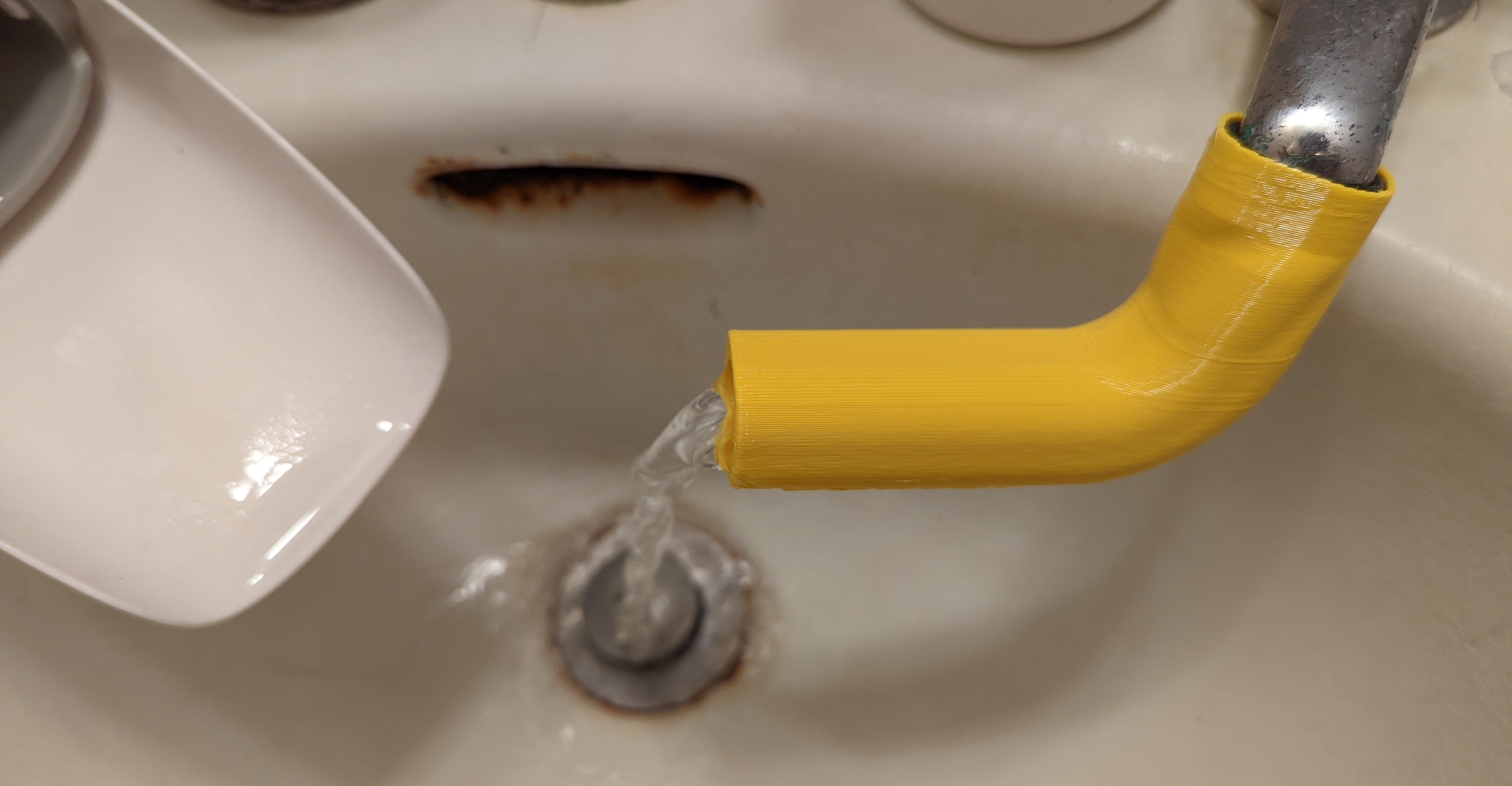
With these measurements, I drafted a quick model that would test the fit of my piece against the faucets’ ends. I decided I was going to print the model in PETG, because it’s pretty easy to print, and is more heat and humidity-resistant than PLA. In order to ensure a snug fit between the 3D-printed parts and the metal faucet ends, I opted to incorporate an intermediate o-ring into the model. I got this handy o-ring assortment from a Home Depot trip. I found that the size 12 o-ring made a good fit against the faucet ends, so I based my design on those rings sizes. I printed the test fit piece in a loud yellow colour.
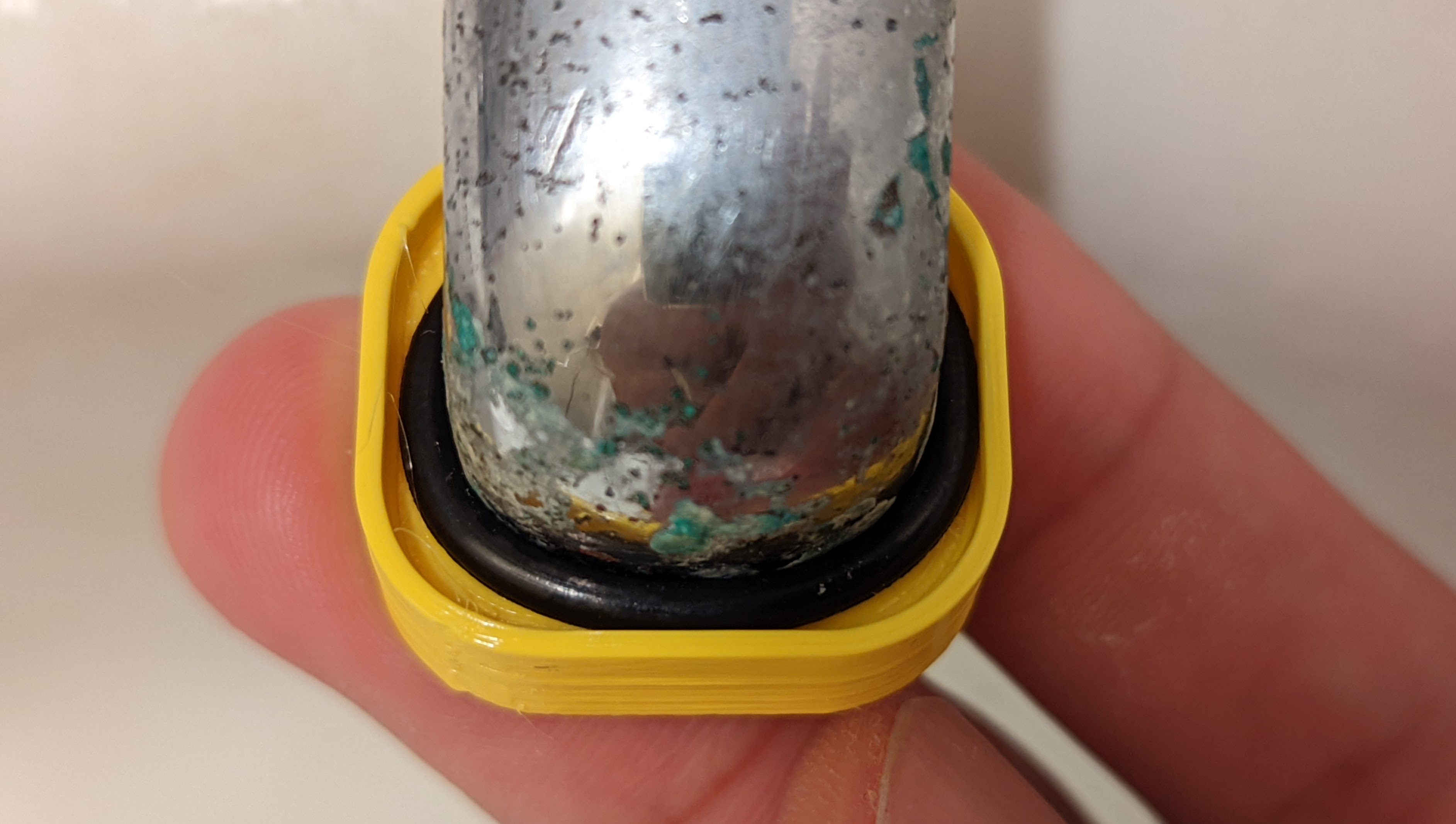
The first test piece was a little too loose, and the piece failed to fit snugly against the faucet end. So I made some minor adjustments, and tada! The second test fit piece came out perfect ![]() !
!
Now that the part involving the most trial and error was complete, I measured out the approximate range of lengths that might fit between the faucet ends and the middle of the sink. I then drafted and printed a model with the corresponding measurements.
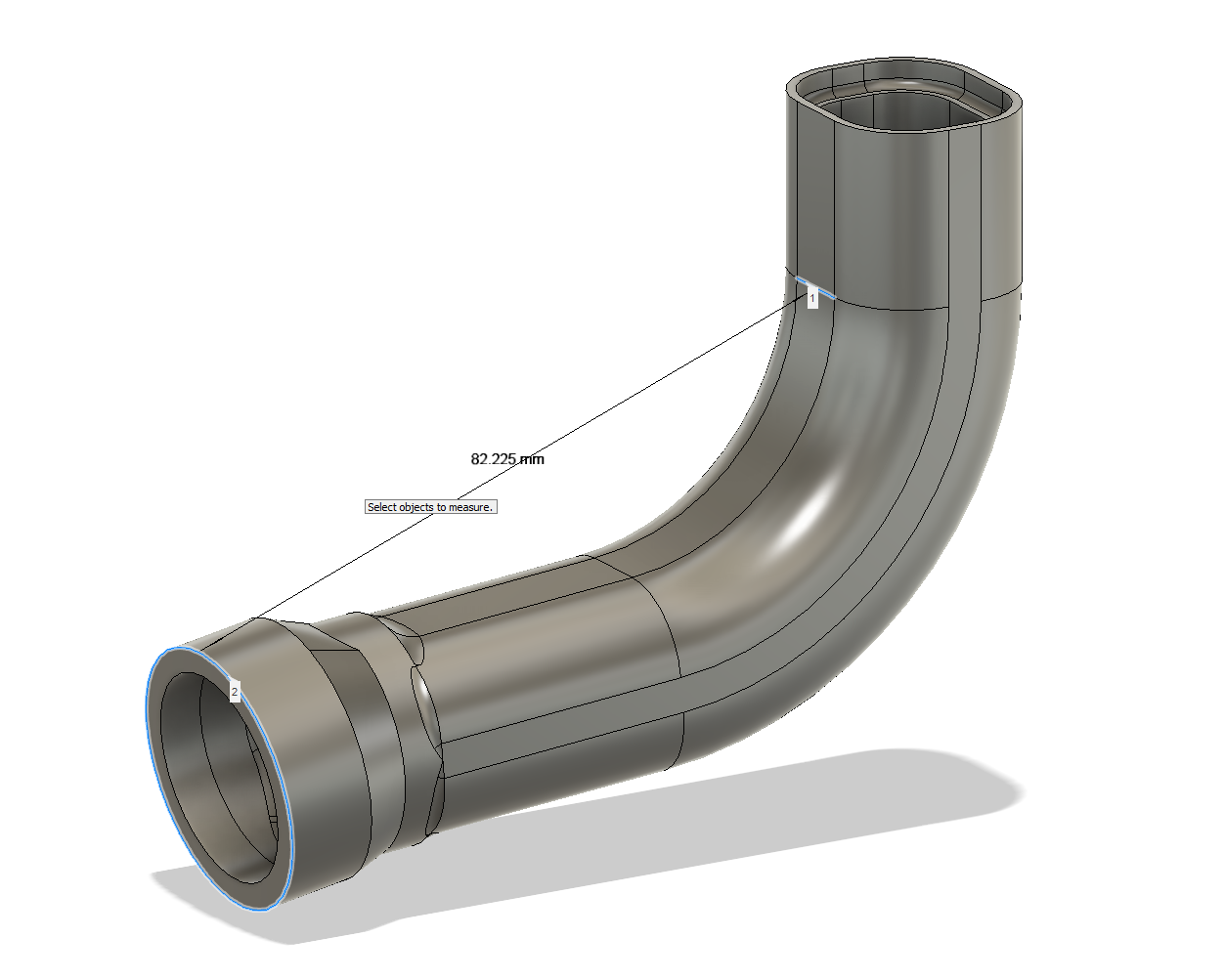
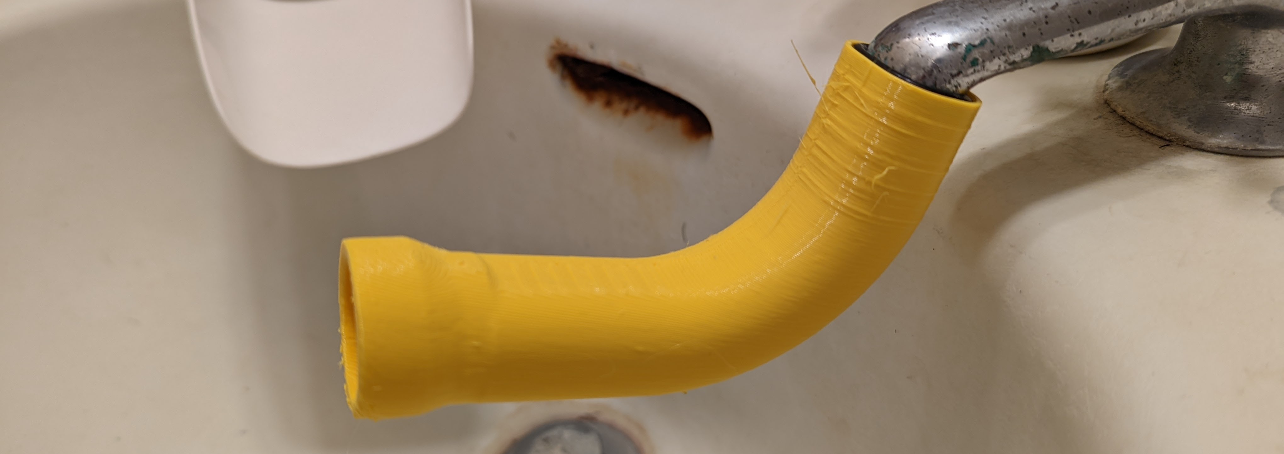
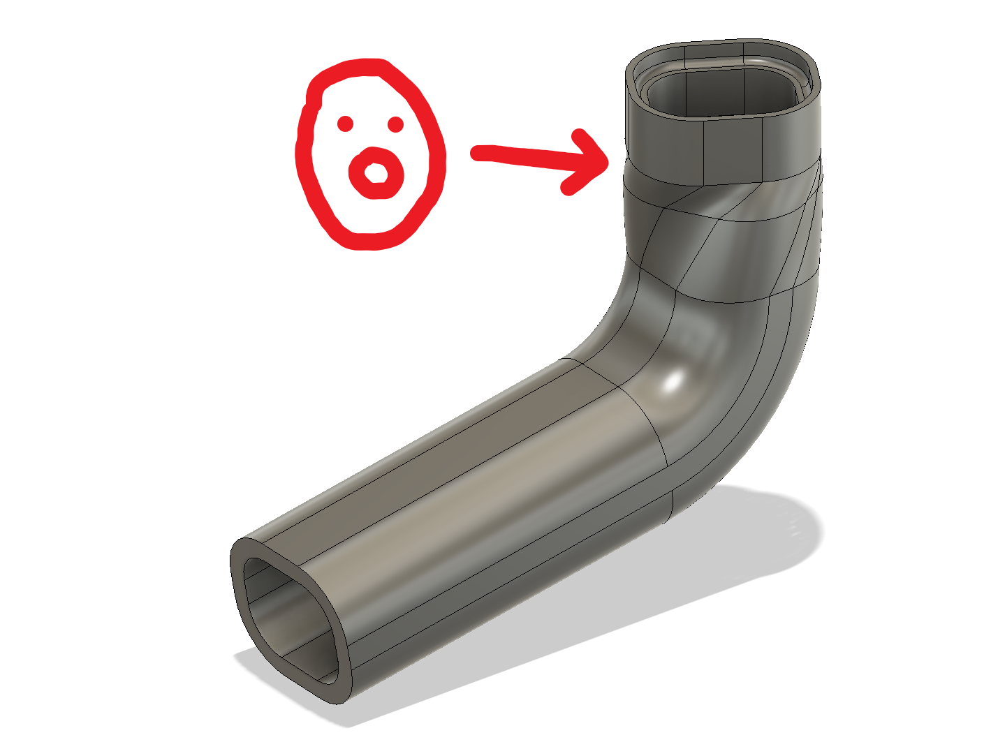
The piece was fine, minus the fact that I didn’t add any angle to the ‘yaw’, if we label the water’s downward flow as the z-axis. So I added to the piece, a twist about the z-axis. This way, I should end up with more usable sink space.
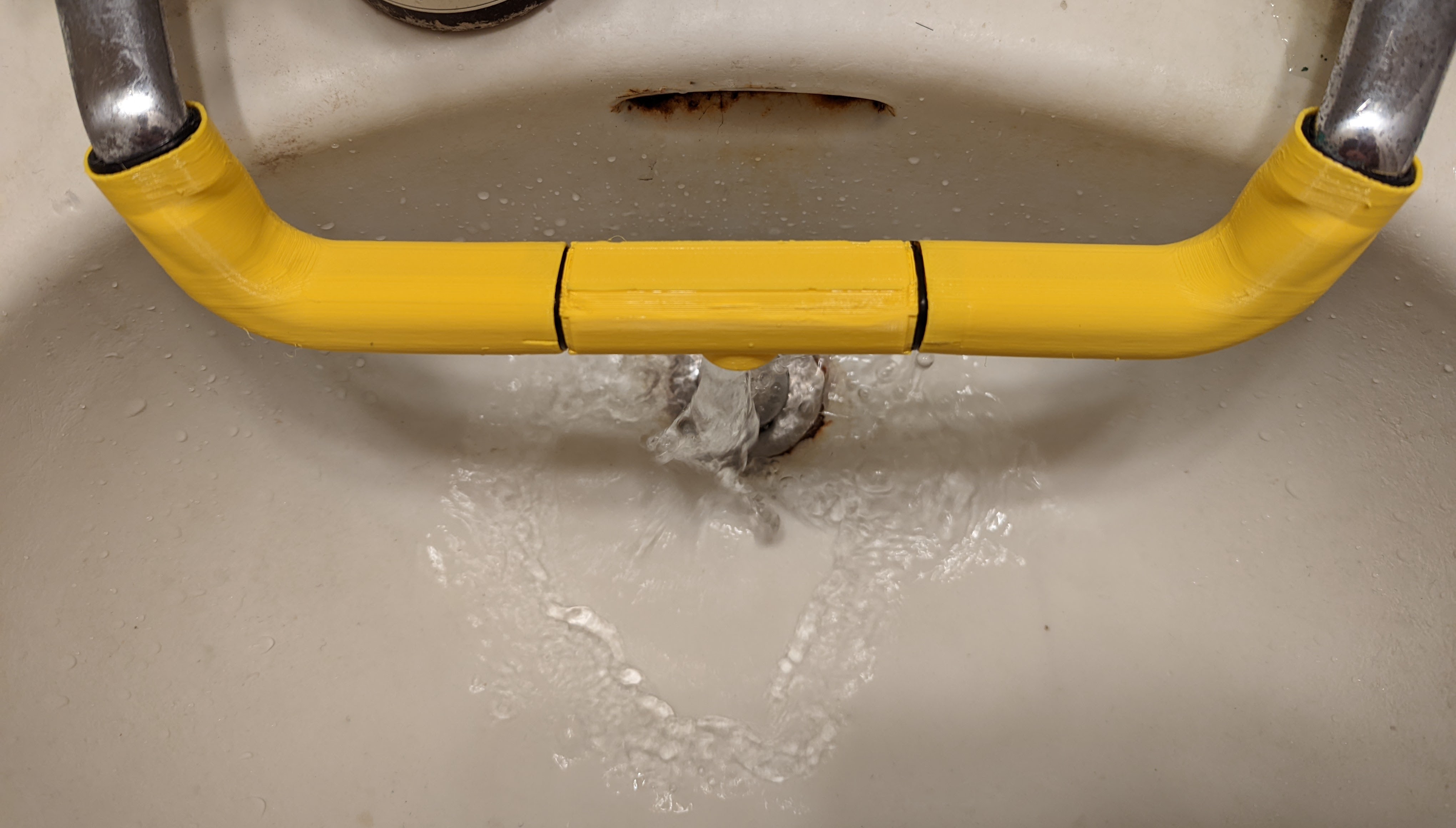
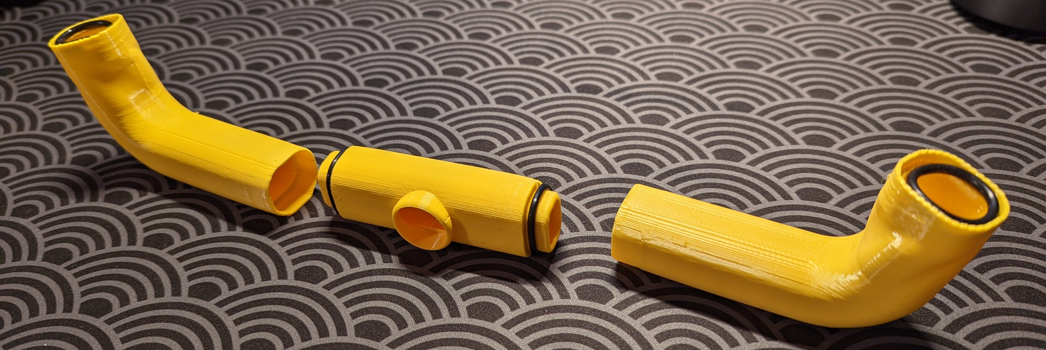
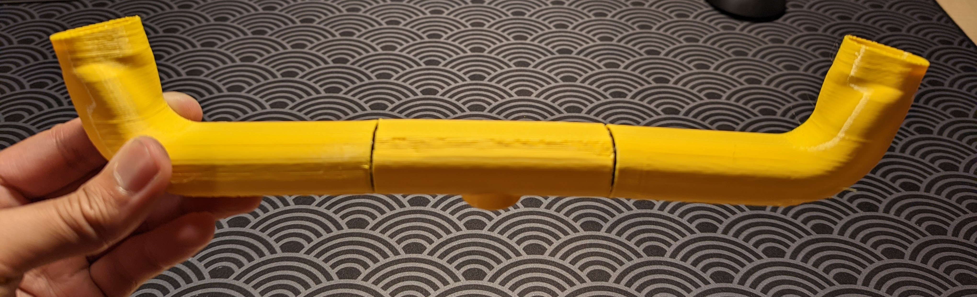
I think the resultant piece is pretty successful! I printed a mirrored copy for the other faucet.
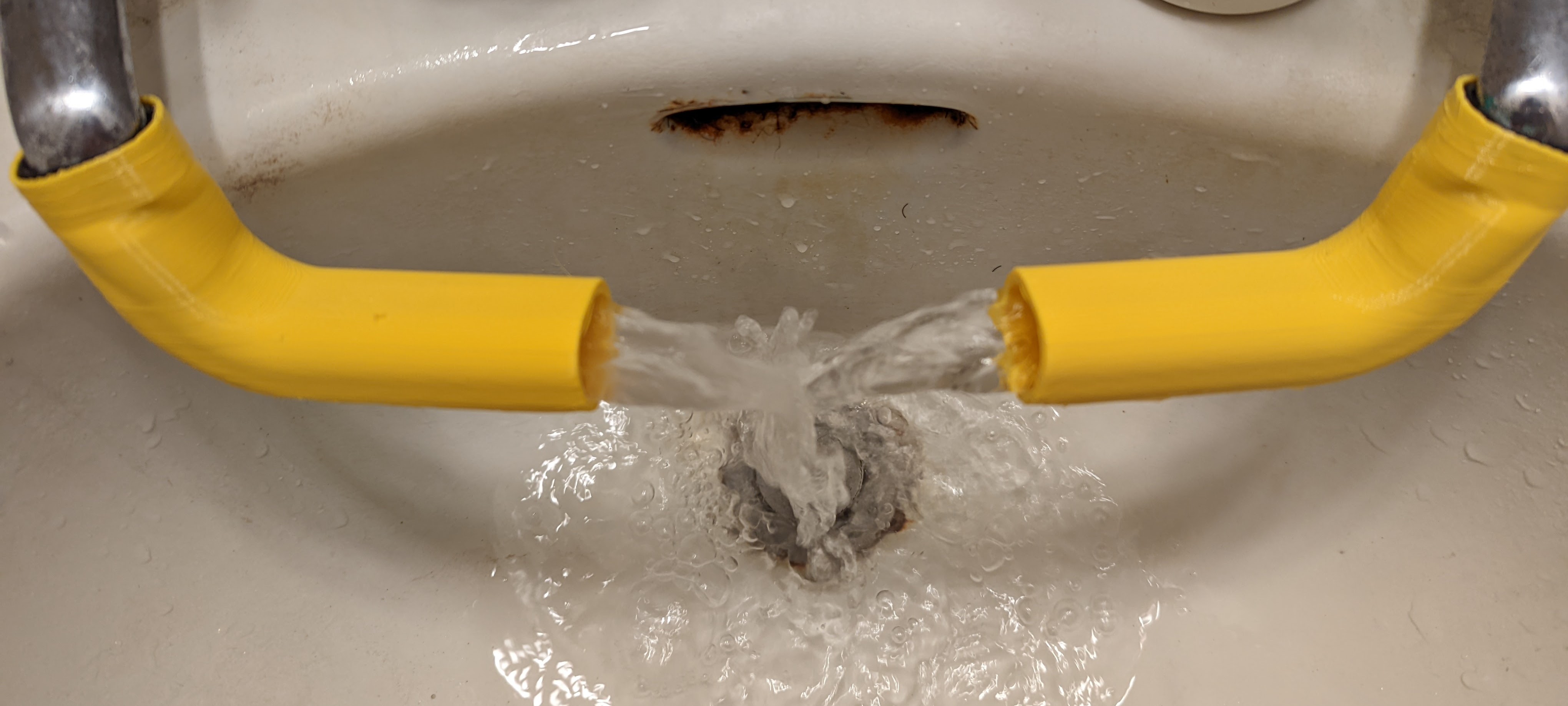
The mixing of the hot and cold water is pretty good, but not great. I think if I add a third piece that joins the two faucet extenders, and acts kind of like a tee junction, I’ll get a pretty decent mixing event in the middle. Back to CAD land!
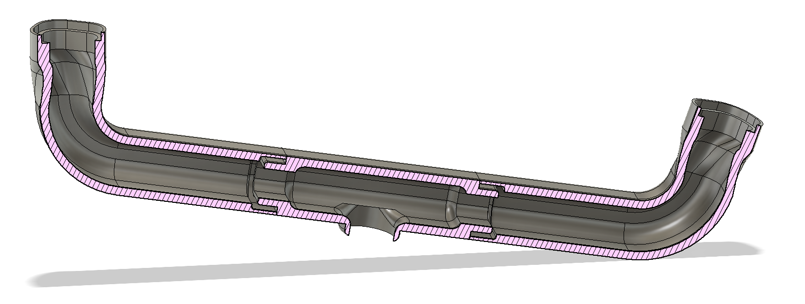
The resulting print turned out alright. The pieces don’t fit super snugly together, but they fit well enough, and everything is functional—the hot and cold water mix great, and I can easily reach the resulting warm water. I am using more #12 o-rings to fit the pieces together.
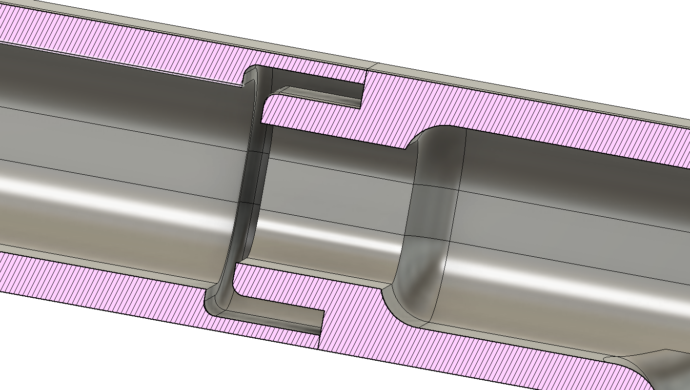
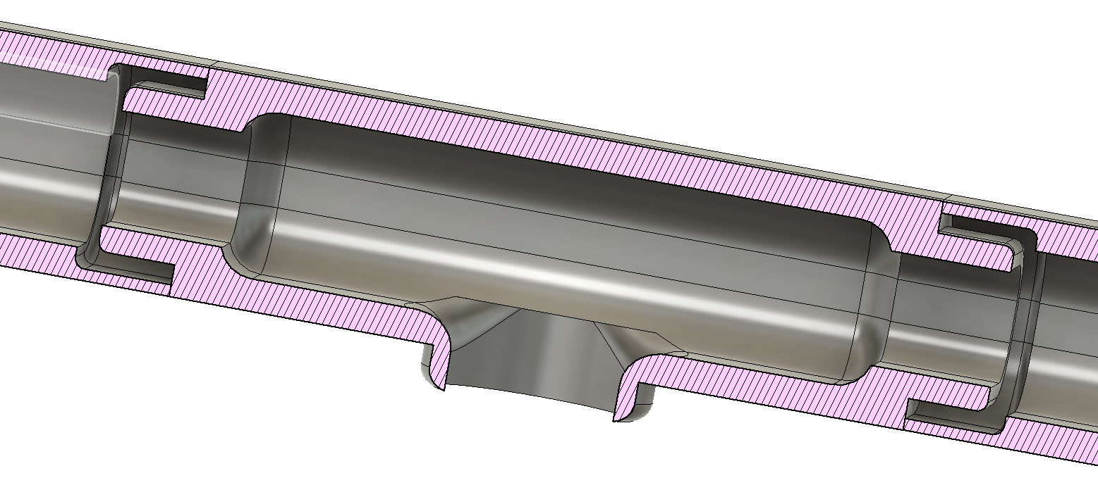
After using this set-up for a few days, my animal instincts got the best of me, and I decided to improve upon the assembly. I really wanted a nice snug fit between the assembly pieces. So I drafted a different junction:
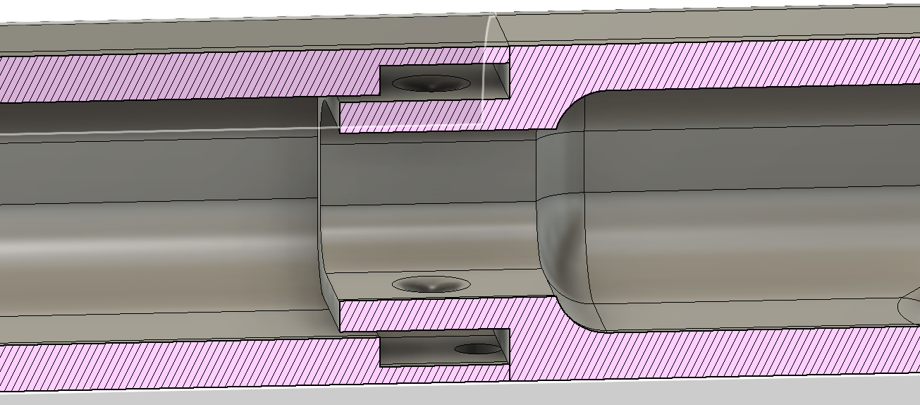
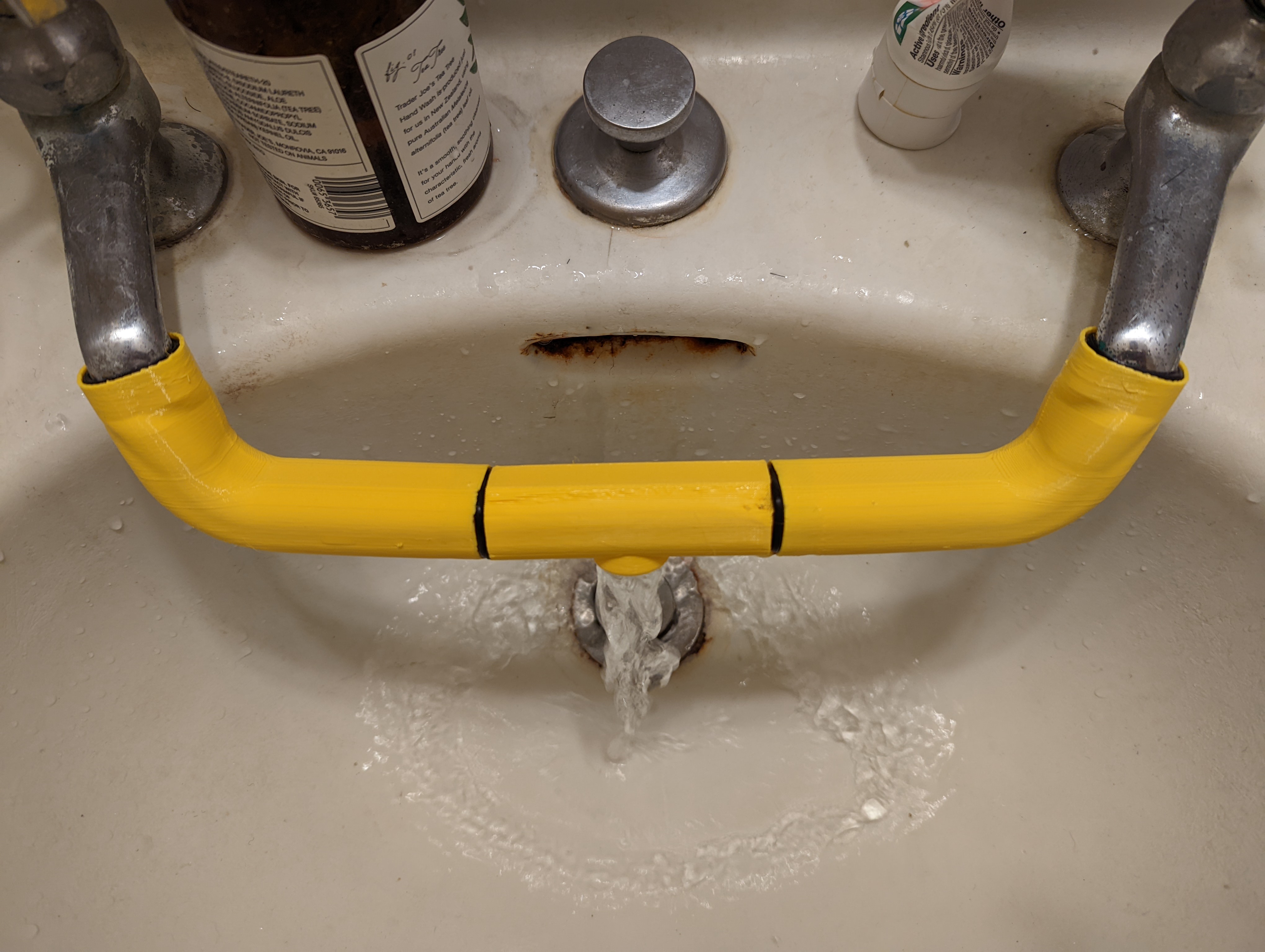
The result seemed pretty decent! The pieces fit together snugly.
The entire assembly fits nicely in the washroom and gets the job done!