I built my very first keyboard from scratch on March 28, 2021 (a little more than year ago now). It was the Void 40, which is a handwired 40%, and I’m actually using it right now to type this post1. When I first built the board, I didn’t think I’d actually use it. I thought that, at best, the board would be a fun weekend project that would teach me about matrix circuits, and at worst, it would be a neat talking piece. The keyboard turned out to be so comfortable, however, that I quickly became very smitten with the 40% ortholinear universe.
At the time of the build, I wrote up everything I did in a private Notion article, but I thought that the write-up would also make for a decent blog post. I relied on blog posts a lot2 to build my Void 40, so it feels only right that I pass the favour forward, and share my silly notes. In this post, I more or less copy my Notion article that details how I built my handwired 40% keyboard.
Materials
Most of these materials can be swapped out for something else. For example, an Arduino Pro Micro can be swapped for something else with the same pinout and footprint. In addition, you’re going to want access to a 3D printer, as well as some common electronics components. Namely, solid core wires, a ribbon cable, a soldering iron, solder, and wire strippers. Preferably, the wire strippers should have enough resolution that it can strip the individual wires off the ribbon cable. Something like this will work perfectly.
| Name | Vendor | Notes |
|---|---|---|
| Switches | ~ | Just make sure they’re Cherry MX-style switches. Switches are a very personal decision. Know also that once you install handwired switches, they’re damn hard to open up and lube. So if that’s something you’re interested in, do that first! |
| Arduino Pro Micro clone | Amazon B01MTU9GOB | Any clone will do. I started off with a typical clone, but I later swapped to this Sparkfun board, because it uses UBS-C. |
| EC11 rotary Encoder | Adafruit 377 | EC11 rotary encoders can be sourced from other places too, like Amazon. I just put in Adafruit SKU here, because it’s less likely to be discontinued than some random Amazon or eBay link. |
| Knob | ~ | I actually printed my knob from here. But any knob that’s meant for a 6 mm shaft should work. Guitar knobs tend to be this size, so if you search for “guitar knob”, you’re likely to find something nice that works. Aluminum knobs are quite nice, for example. |
| 1N4148 diodes | Amazon B06XB1R2NK | Again, can be sourced from lots of places. |
| Keycaps | ~ | Just make sure they’re for Cherry MX-style switches. Keycaps are a very personal decision. If possible, try and get something geared towards an ortholinear 40% board. If you search “ortholinear keycaps”, a bunch of decent ones will come up for cheap. |
| M3 countersunk screws (90 deg taper) | McMaster 91294A130 | M3, 0.5 mm pitch, 10 mm length, 90 deg countersink; need 4 for front of keyboard |
| M3 x 10 mm sockethead screws | McMaster 91290A115 | M3, 0.5 mm pitch, 10 mm length, need 2 for back bottom of keyboard |
| M3 x 16 mm sockethead screws | McMaster 91290A120 | M3, 0.5 mm pitch, 10 mm length, need 2 for back top of keyboard |
Assemble the Keyboard’s ‘Body’
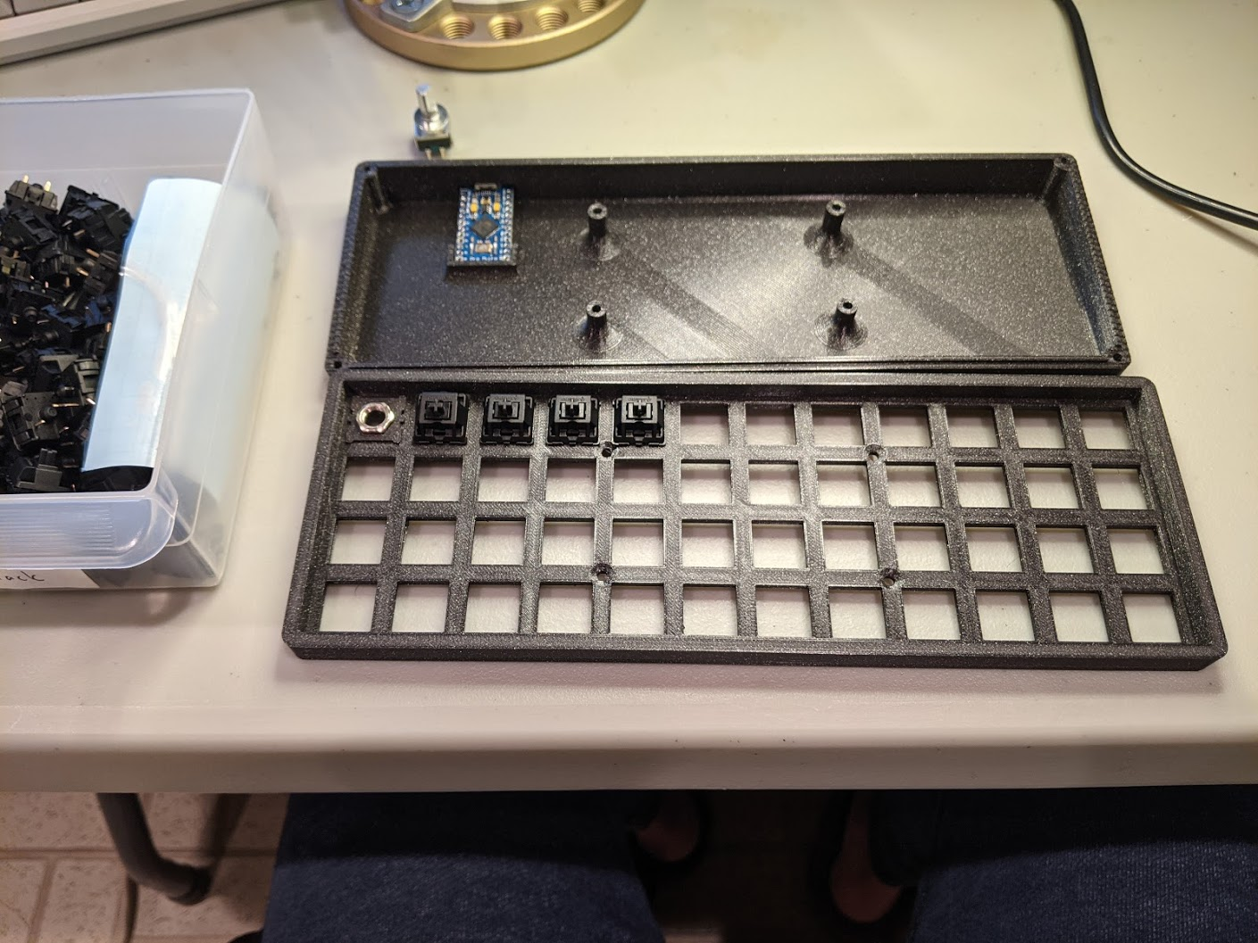
I started off by printing the case and the switchplate. I used the Void40 design, in combination with some handy MX-style to EC11 rotary encoder adaptors for my EC11 rotary encoder. I used Prusament PLA in Galaxy Black for everything. For switches, I’m using Cherry MX Blacks (stock, not lubed).
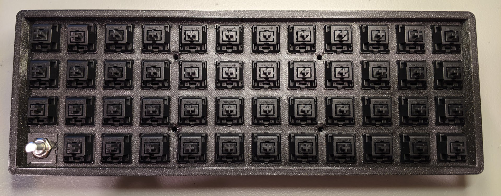
Popping in the MX switches makes a very satisfying snapping sound.
The keyboard is all socketed!
Connect the Keyboard’s Electronics
![]() FYI:
FYI: ![]() The next few steps will have us working with the keyboard’s electronics. For these parts, some understanding of how a keyboard matrix works is good. This old webpage is tried and true. This other old webpage provides some elucidating gifs. In short, we’re scanning the rows and columns, looking for interruptions. The coordinates of the interruption are defined because the keyboard connections form a matrix.
The next few steps will have us working with the keyboard’s electronics. For these parts, some understanding of how a keyboard matrix works is good. This old webpage is tried and true. This other old webpage provides some elucidating gifs. In short, we’re scanning the rows and columns, looking for interruptions. The coordinates of the interruption are defined because the keyboard connections form a matrix.
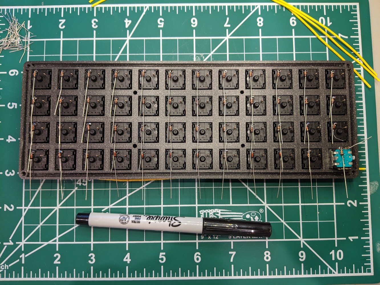
We start by hooking up the 1N4148 diodes. All handwiring guides suggest looping the diodes and then slipping them onto each switch. Then solder each diode on its switch.
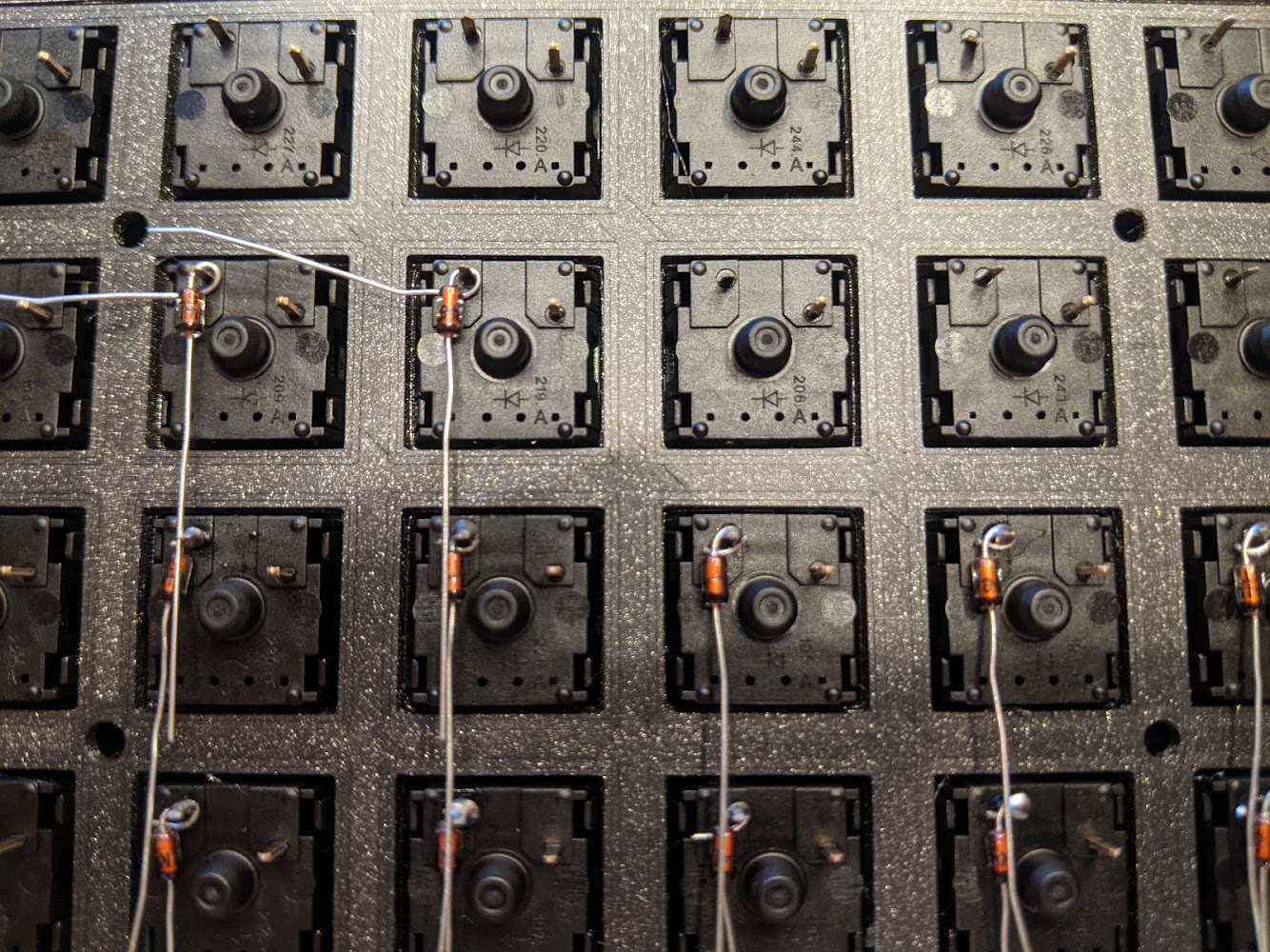
We solder all the diodes. We cut off the anode ends of the diodes. We treat the 2-pins on the rotary encoder in the exact same way, as we would a regular switch.
We now have to hook up the rows of our keyboard matrix. To do so, mark the points that need to be cut with a Sharpie. Most tutorials then recommend peeling the parts that need to be exposed, via an Exacto knife. I find that using a wire stripper to strip off all the bits of insulation, and then slipping back on half of them is much more efficient and less finicky.
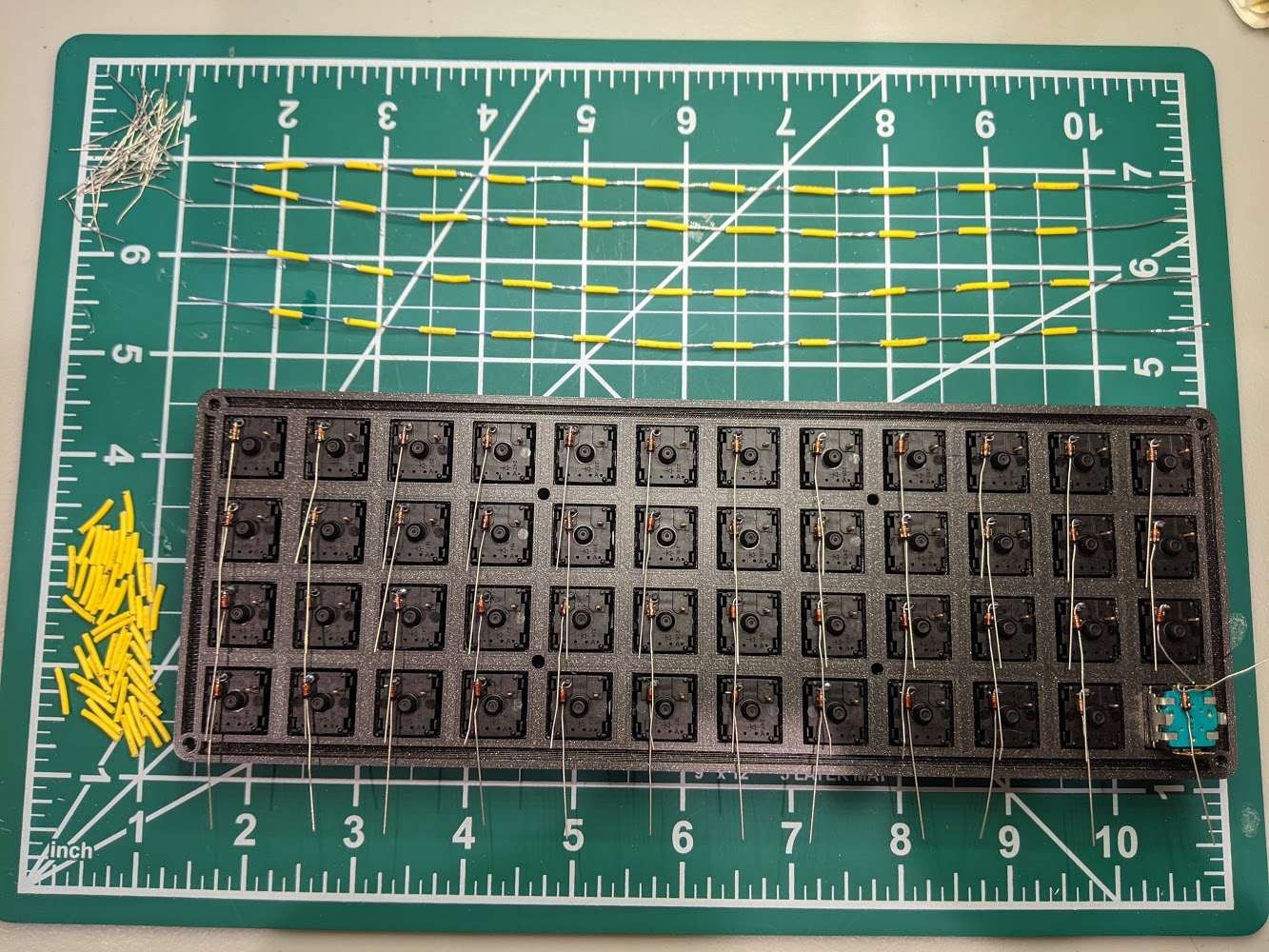
We then position each row wire, and stabilize the connection by bending the cathode end of the diode up. We then solder the connection and cut the cathode lead:
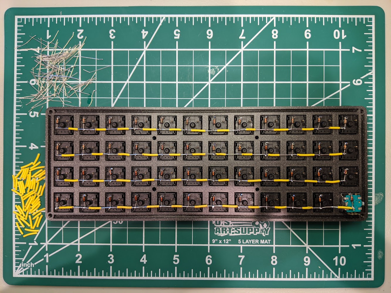
We next work on the column wires of the keyboard matrix. I found this part more difficult for some reason … maybe just because I had to do more? I think part of it was also because the insulation segments I had to strip off were a little bit longer than the ones for the row matrix, which may have made slipping them on and off more resistive, in terms of friction.
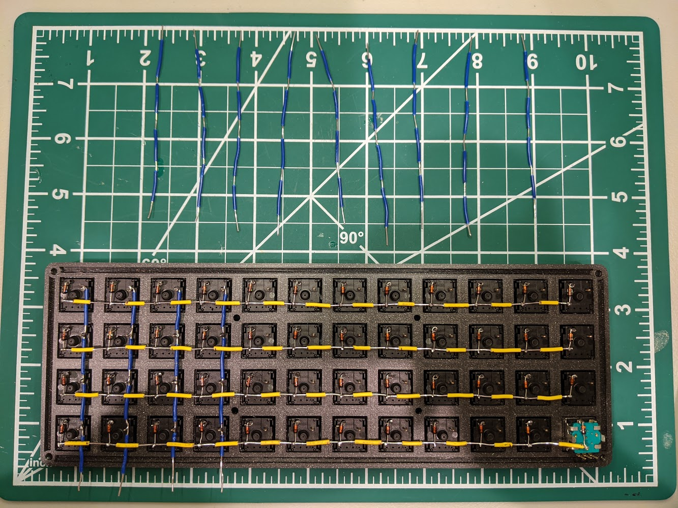
When positioning the column wires, tuck them underneath the row wires. The column wires should be nice and secure between the switch plate and the row wires. The complete matrix might look something like so:
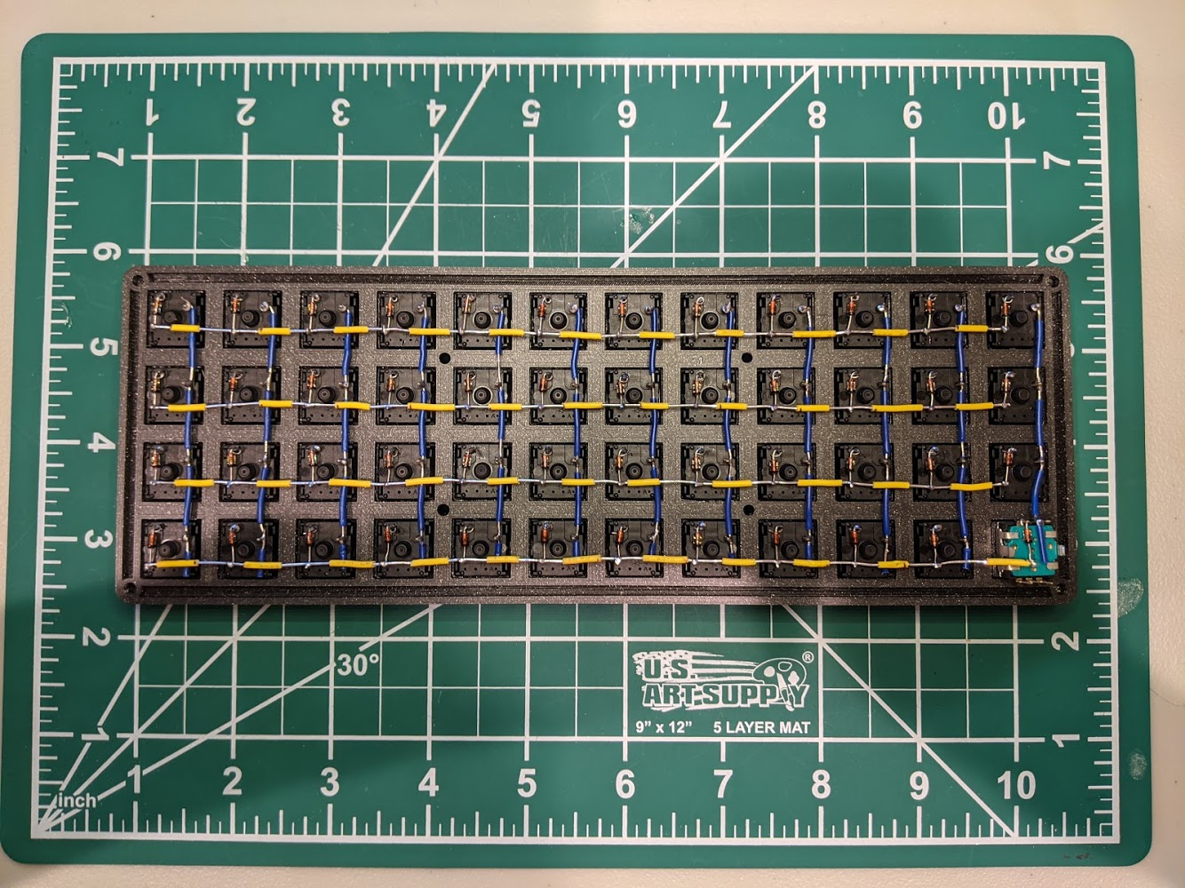
To hook up these connections, I used a pair of tweezers to wrap the ribbon cable’s wiring around each row or column. Then, I soldered the connection in place. The other end of the ribbon cable solders directly to the microcontroller. QMK names the microcontroller pins of the Arduino Micro in kind of a strange way. The legend for those labels is listed below:
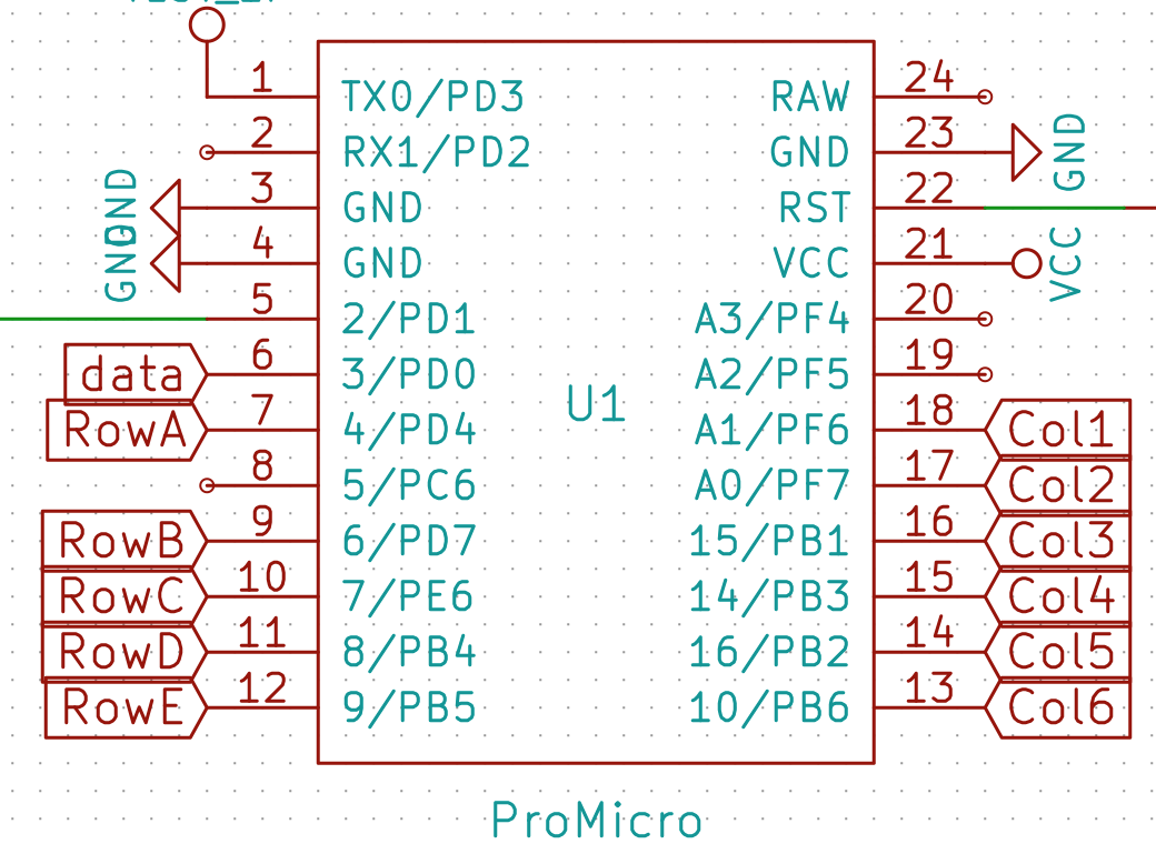
Given these labels, connect the specified row and column to the respective microcontroller pin. The QMK pin names are provided:
| Pro Micro Pin | Row |
|---|---|
| C6 | Top row (QWER . . .) |
| D4 | Second row (ASDF . . .) |
| D0 | Third row (ZXCV . . . ) |
| D1 | Fourth row (ctrl, GUI, alt . . .) |
| Pro Micro Pin | Column (Left to Right) |
|---|---|
| E6 | 1 |
| D7 | 2 |
| B6 | 3 |
| B4 | 4 |
| F6 | 5 |
| F7 | 6 |
| F4 | 7 |
| F5 | 8 |
| B1 | 9 |
| B3 | 10 |
| B2 | 11 |
| B6 | 12 |
| Pro Micro Pin | Rotary Encoder Pin |
|---|---|
| D2 | Right most pin of the three pins |
| GND | Centre pin of the three pins |
| D3 | Left most pin of the three pins |
![]() FYI
FYI ![]() : The rotary encoders don’t super matter. Just make sure GND is definitely GND (it’s by design that the GND pin on the rotary encoder is the middle pin . . . you can’t swap it accidentally and make an asymmetry mistake). If you swap D2 and D3 around, you can just go into
: The rotary encoders don’t super matter. Just make sure GND is definitely GND (it’s by design that the GND pin on the rotary encoder is the middle pin . . . you can’t swap it accidentally and make an asymmetry mistake). If you swap D2 and D3 around, you can just go into config.h and swap the values for ENCODERS_PAD_A and ENCODERS_PAD_B.
The following code shows the pin definitions for ENCODERS_PAD_A and ENCODERS_PAD_B. Swapping the pins will alter the clockwise and counter-clock direction effects.
#define ENCODERS_PAD_A { D2 }
#define ENCODERS_PAD_B { D3}
#define ENCODER_RESOLUTION 4
#define TAP_CODE_DELAY 10
Once you’ve finished making all the electrical connections, leave the keyboard bare and open! You’re going to want to test the keyboard out while eveything’s still exposed. That way, if a poor solder joint is causing a faulty switch, or if a pin is miswired, you can still fix the issue pretty easily. Opening up the case everytime there’s a problem is going to get real old, real fast.
The final keyboard connections might look something like the below.
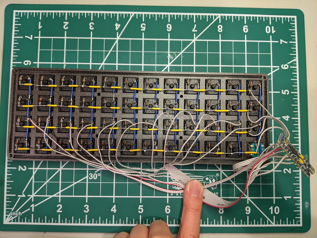
Just kidding, the final keyboard connections shouldn’t resemble the above image, because I soldered the ribbon cable wires onto the bottom of the µC, instead of the top. I had to resolder the ribbon cable onto the top of the µC, because otherwise, the µC won’t fit into its insert at the bottom of the keyboard case.

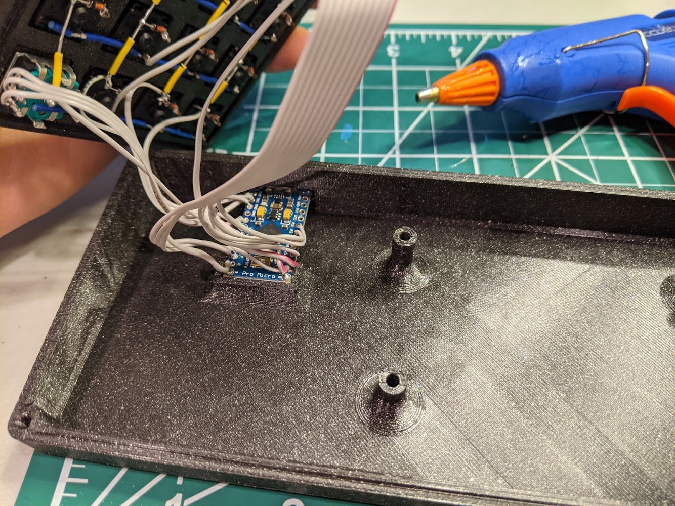
I then place a dab of hot glue onto the bottom of the µC insert, to secure the µC in place. To be honest, the hot glue isn’t actually necessary, but it doesn’t hurt either, so I figured why not? You’ll be tempted, but do not close the keyboard case yet.
We now test the keyboard matrix, to make sure there aren’t any weak connections. To test, we simply flash the code for the Void403. My code and keymap for this build can be found on my fork of QMK.
![]() FYI
FYI ![]() :
The very, very first time you flash the firmware, you must momentarily short the VCC and GND pins, if using a faithful Pro Micro clone (see the docs for your particular µC model to see how to do a hardware reset–some models differ slightly, but a lot of them have a dedicated reset button, which simplifies things). After you flash the firmware for the first time, you can take advantage of the fact that the
:
The very, very first time you flash the firmware, you must momentarily short the VCC and GND pins, if using a faithful Pro Micro clone (see the docs for your particular µC model to see how to do a hardware reset–some models differ slightly, but a lot of them have a dedicated reset button, which simplifies things). After you flash the firmware for the first time, you can take advantage of the fact that the _ADJUST layer of my keymap includes a reset function on the top left key (called QMK_BOOT). According to this possibly outdated GitHub issues page, mapping a reset to the keymap is only possible if the bootloader is caterina.
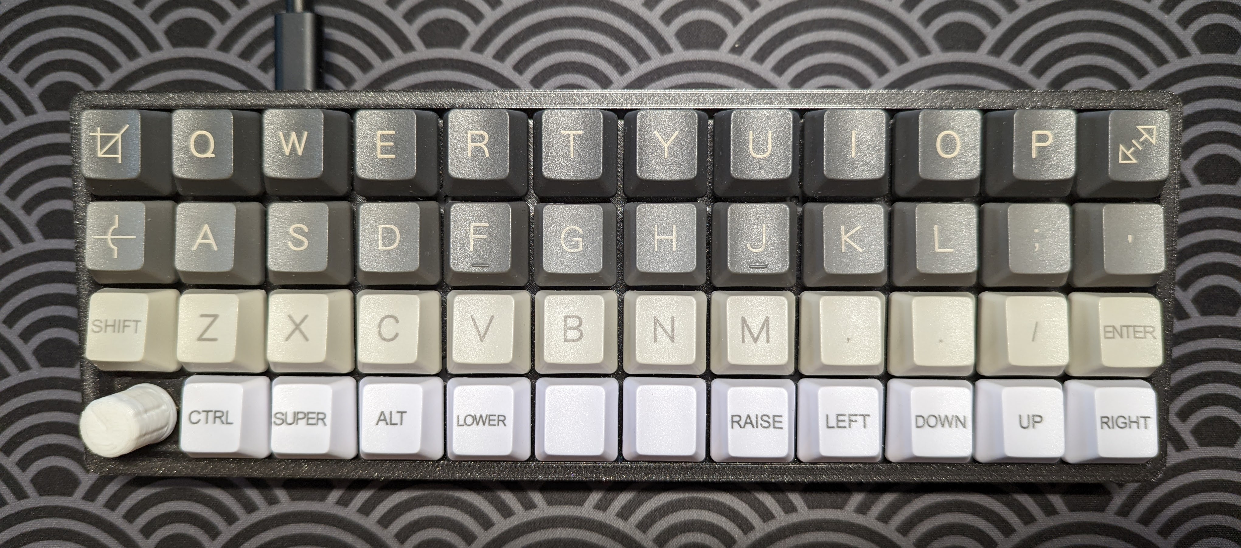
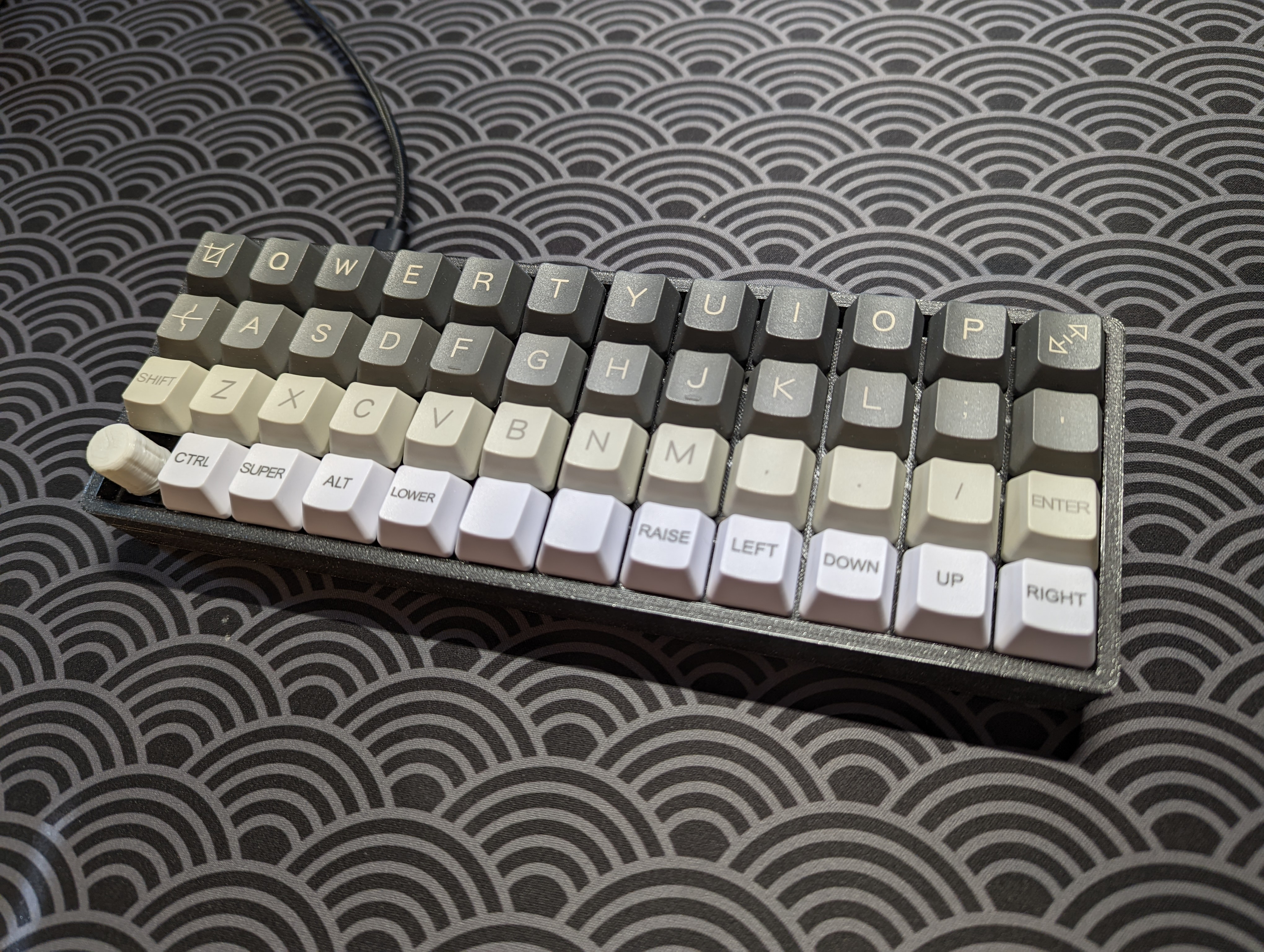
We can finally close up the case and screw everything together! Use the countersunk screws for the top side, the shorter socket head screws for the bottom side’s south edge, and the longer socket head screws for the bottom side’s north edge. Congrats! You’ve just made yourself a handwired 40% keyboard!
Footnotes
-
Admittedly, I’m normally typing on something else, like my Planckneko, but I’m still partial to my Void 40, mostly for sentimental reasons. I think it still sounds and feels really nice. ↩
-
This blog post by Blake Dryson was super useful, and is what I primarily relied on to make this build. This post, this post, this post, this Geekhack post and the official QMK guide on GitHub were also all useful to me. ↩
-
An explanation of QMK and the steps involved to compile and flash a QMK keymap is outside the scope of this blog post. I might write something about QMK in the future, but in the meantime, I suggest you peruse the excellent QMK docs. My QMK-powered firmware is here. ↩