Some close friends of mine own a cheap Velocifire TKL61WS mechanical keyboard. Since they first purchased this keyboard, they’ve gone deep down the mk rabbit hole (of which, I obviously had nothing to do with …), and no longer feel very impressed with the keyboard. I thought it might be a fun project and gift if I modded it for them. This blog post details my modding adventures.
Disassembly
Here’s a photo of the original keyboard with some of its default keycaps still in place. Something of a looker, but not necessarily in the best way:
We start by unscrewing all the screws on the switch plate, which is what’s affixing the plate and the PCB onto the case.
We now need to remove the switches from the PCB. Technically, there are these small ‘hot-swap sockets’ installed onto the PCB (which were not Kailh styles, but were rather low quality Mill-Max style clones), and they had a kind of death grip on the Gateron brown switches. I think these sockets are awful, and I made an executive call to just destroy them, and turn the board into a dependable solder-only board ![]() .
.
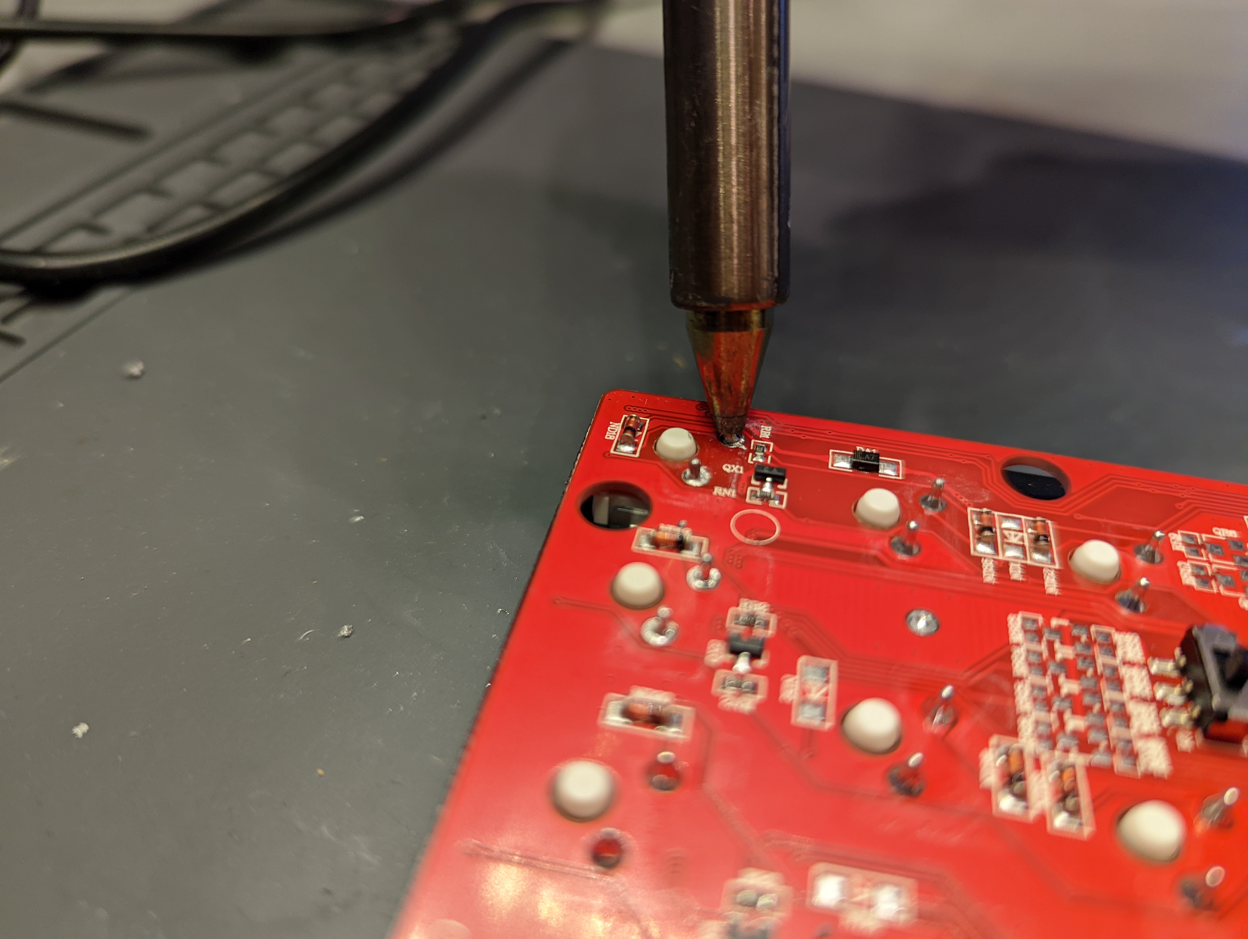
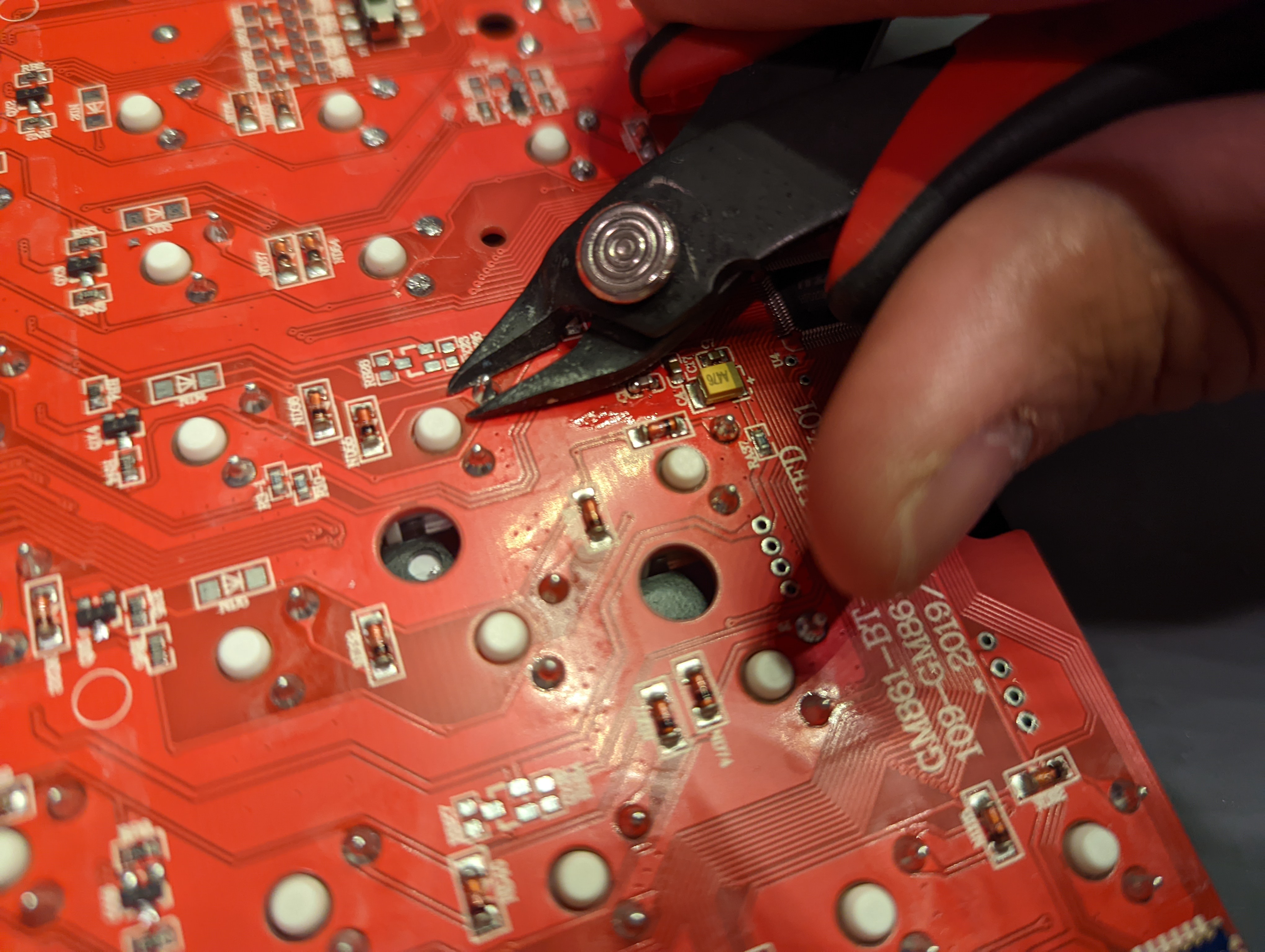
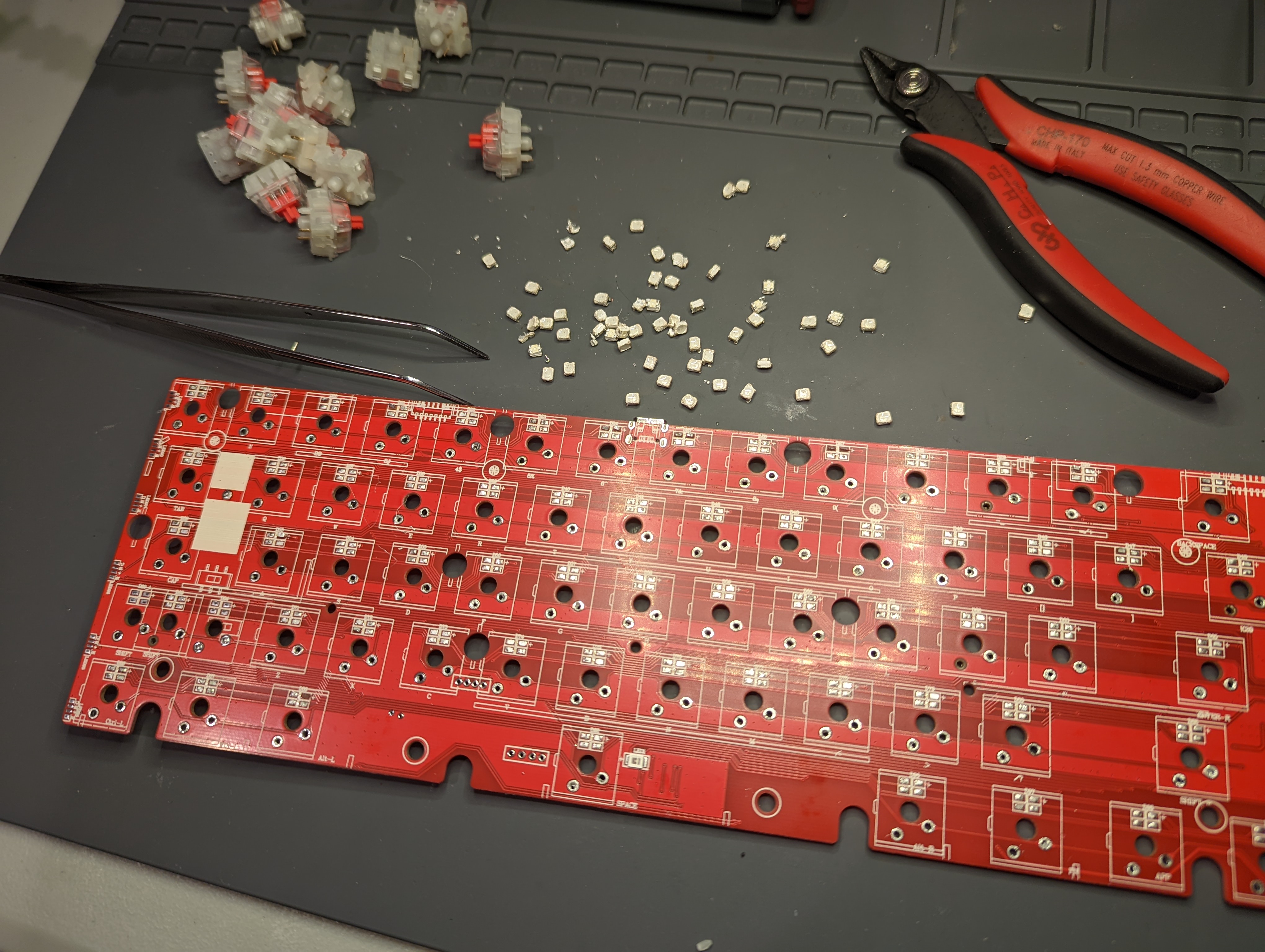
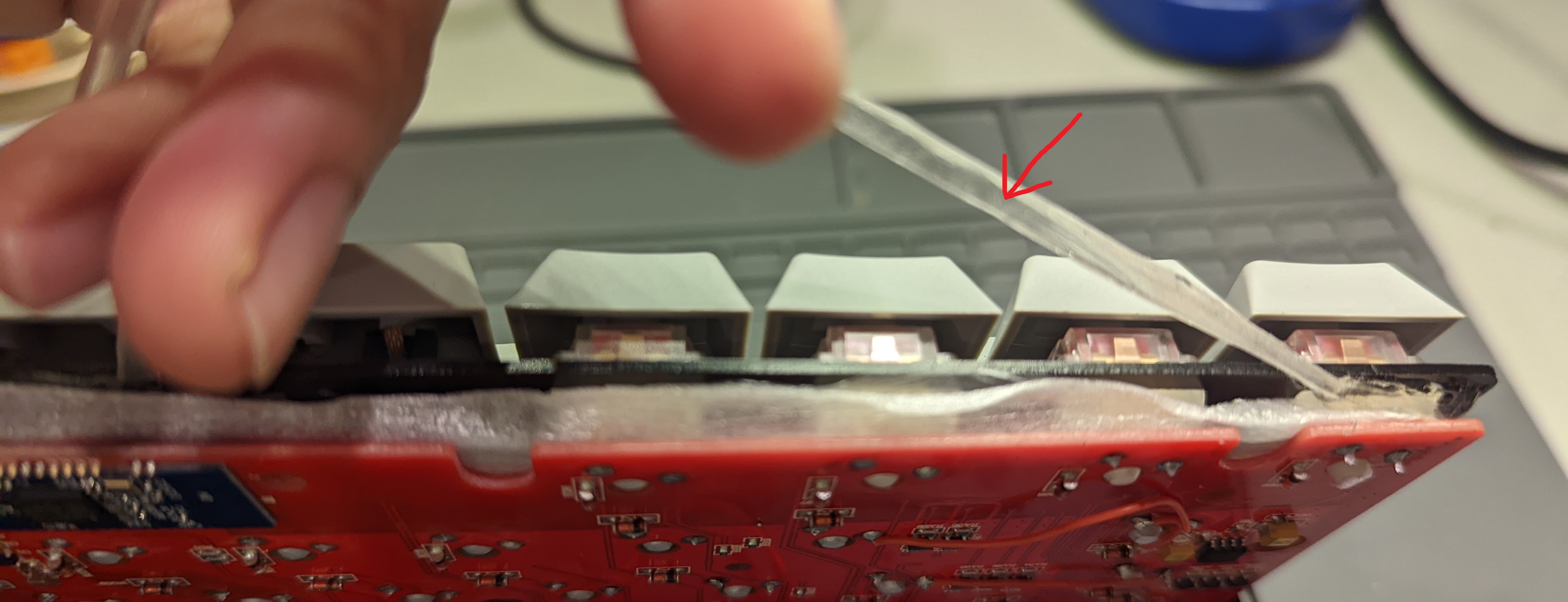
Getting rid of the sockets requires us to snip off the backside of the switch leads with flush cutters, because the added thickness from the sockets are preventing my desoldering gun from getting a good grip on the leads.
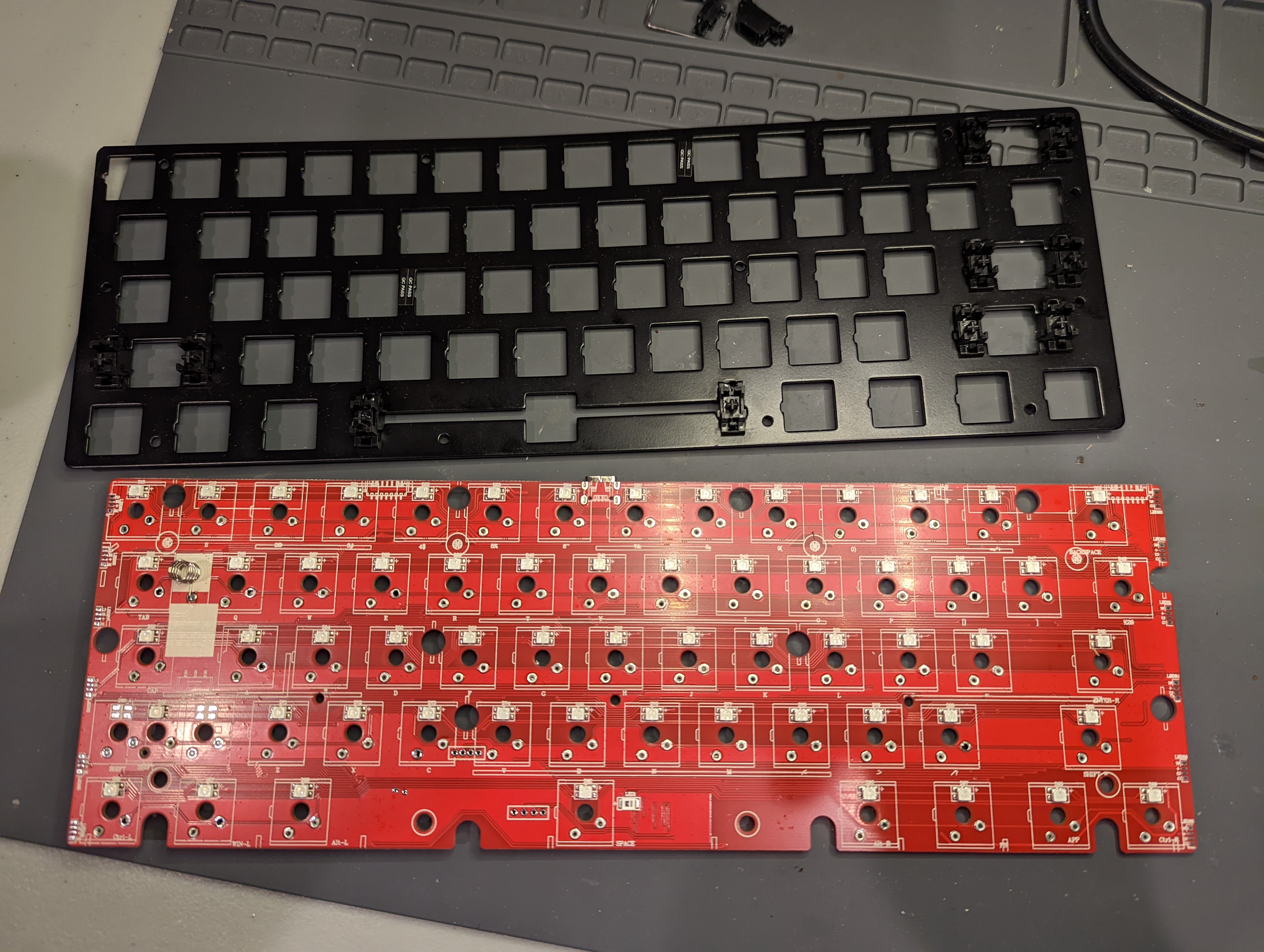
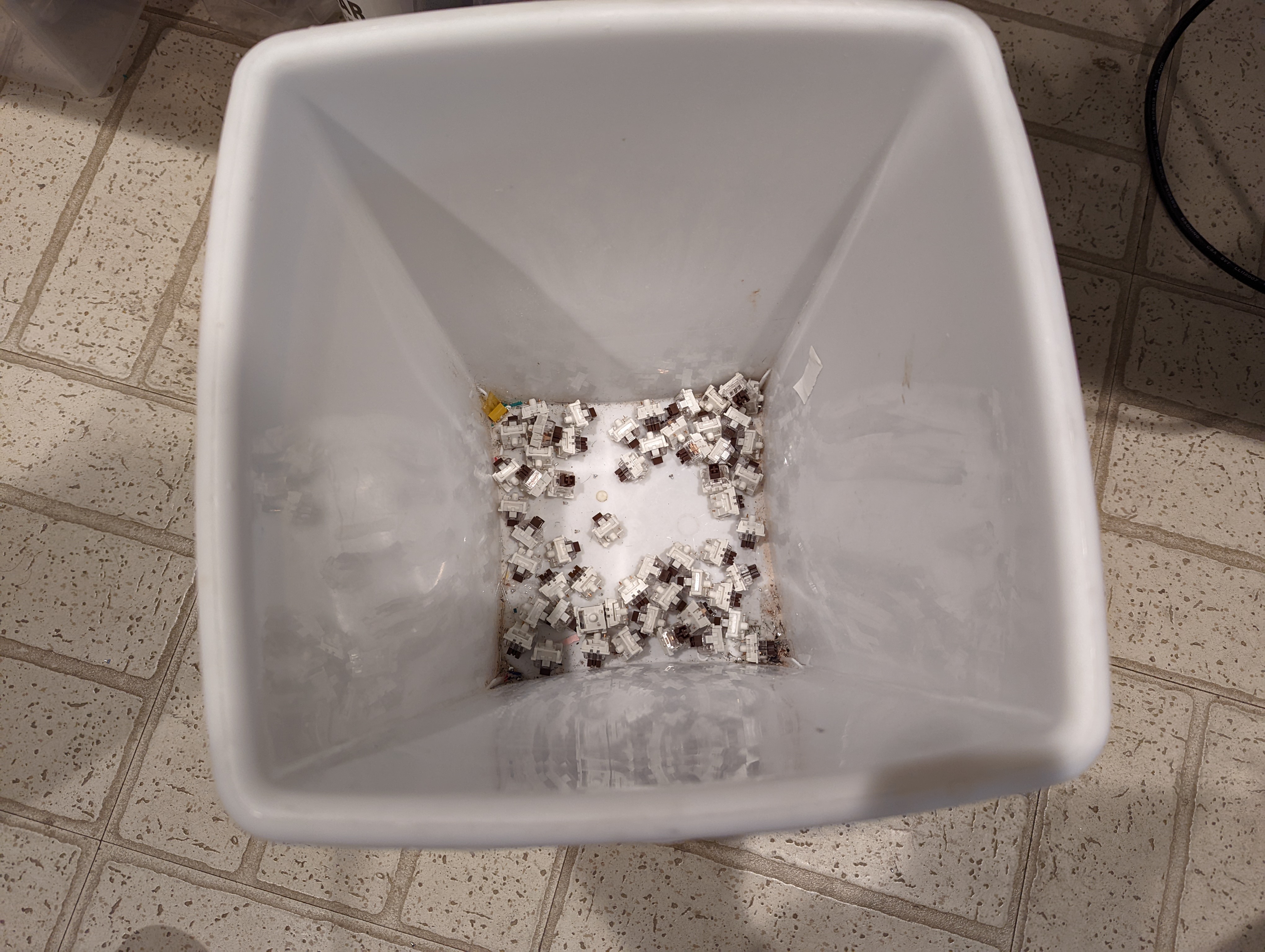
After a decent amount of work, I’ve desoldered all 2 billion switches:
And I’ve had to sacrifice those juicy Gateron brown switches in the process. Can’t say they’ll be missed! ![]()
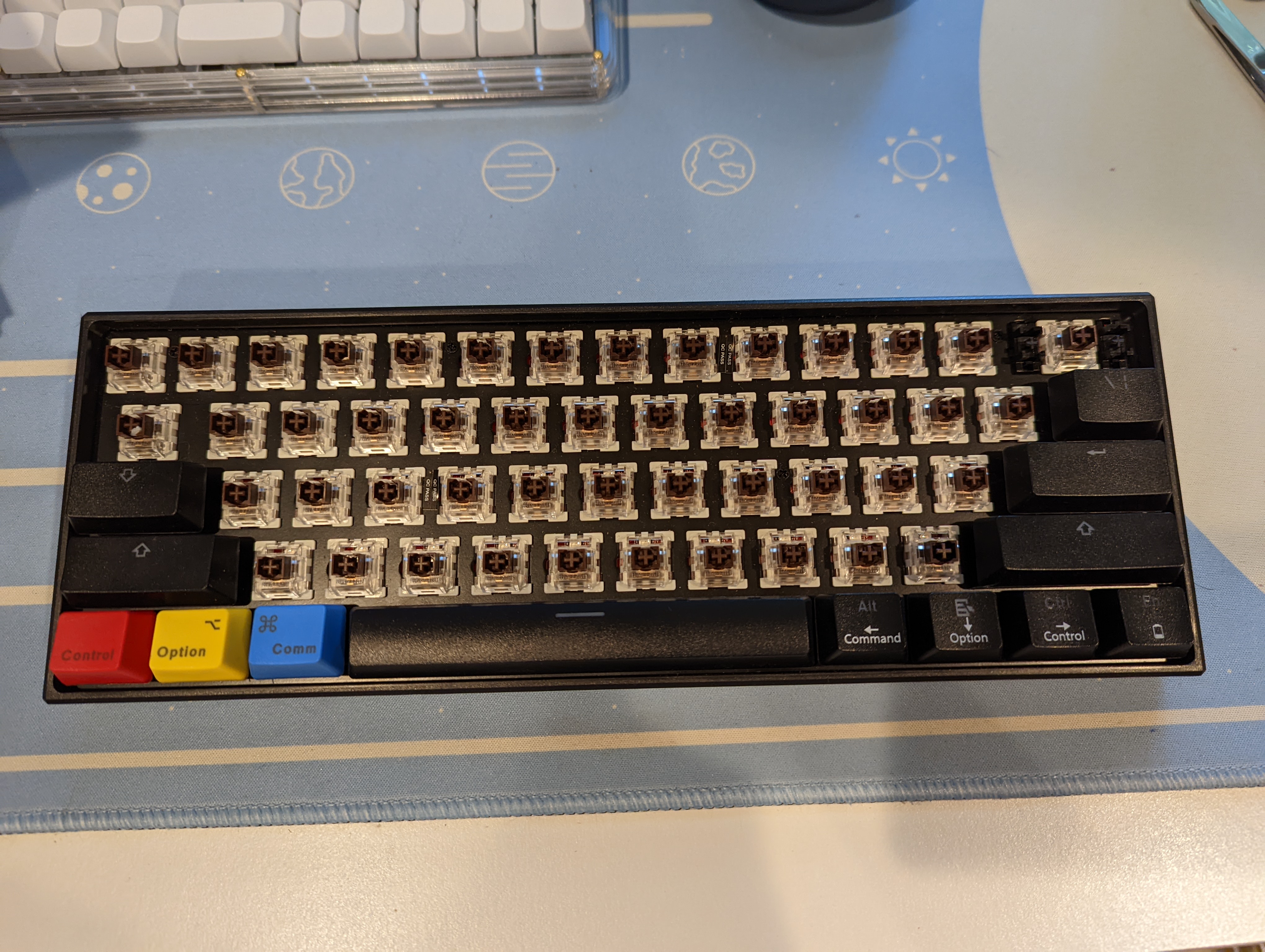
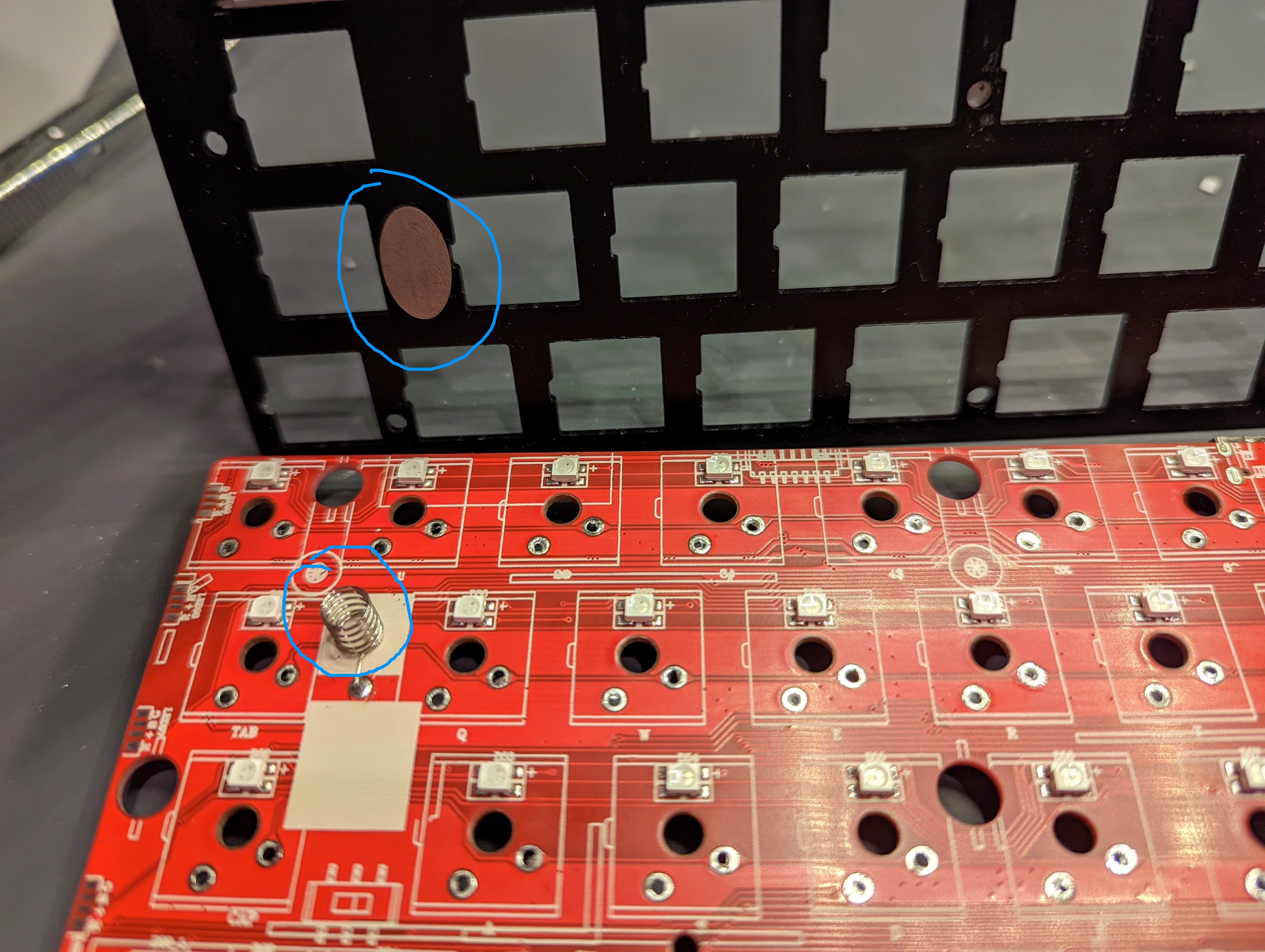
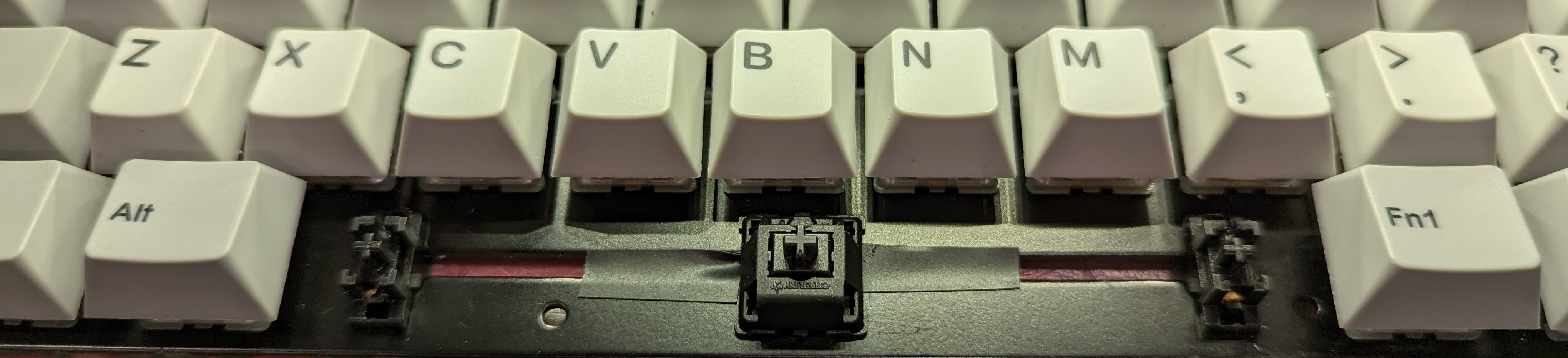
I did notice two unusual features about the board, after I desoldered all the switches. One is that the stabilizers appear to be integrated into the switch plate rather than the PCB, which is definitely atypical. So I’m guessing that means I can’t upgrade the stabs to something like Owlab or Durock stabs. It does mean that I’ll still be able to holee mod and lube the stabs though.
The other is that there appears to be a ‘grounding’ spring on the PCB. It seems to line up directly with an exposed metal contact on the switch plate. Personally, I find this feature to be a little strange … from an acoustic perspective at least, the direct contact of the metal spring onto the metal switch plate is going to result in a lot of pinging sounds. I’ve also just never seen this feature before, and I’ve worked with keyboards with metal switch plates. I think I’m going to desolder the spring and add some padding between the switch plate and the PCB (especially on the exposed part of the plate that’s meant to contact the spring) to a) dampen any kind of unwanted pinging noise, and b) prevent any kind of electrical conductivity between the plate and the PCB.
Add Some Foam between the Switchplate and the PCB
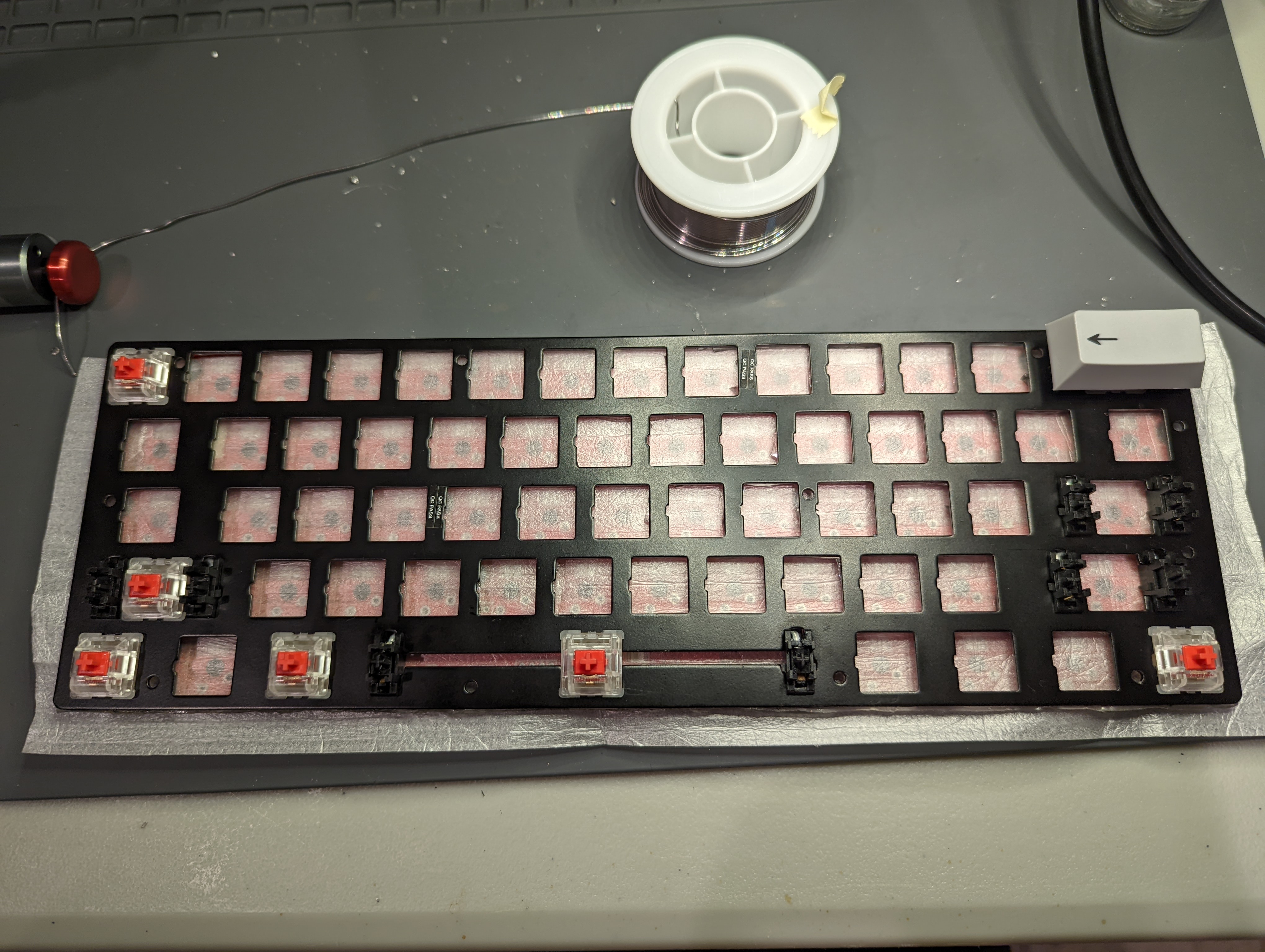
On that note, I decided to cut some double-sided grippy tape to dampen the switch plate-PCB interface sound.
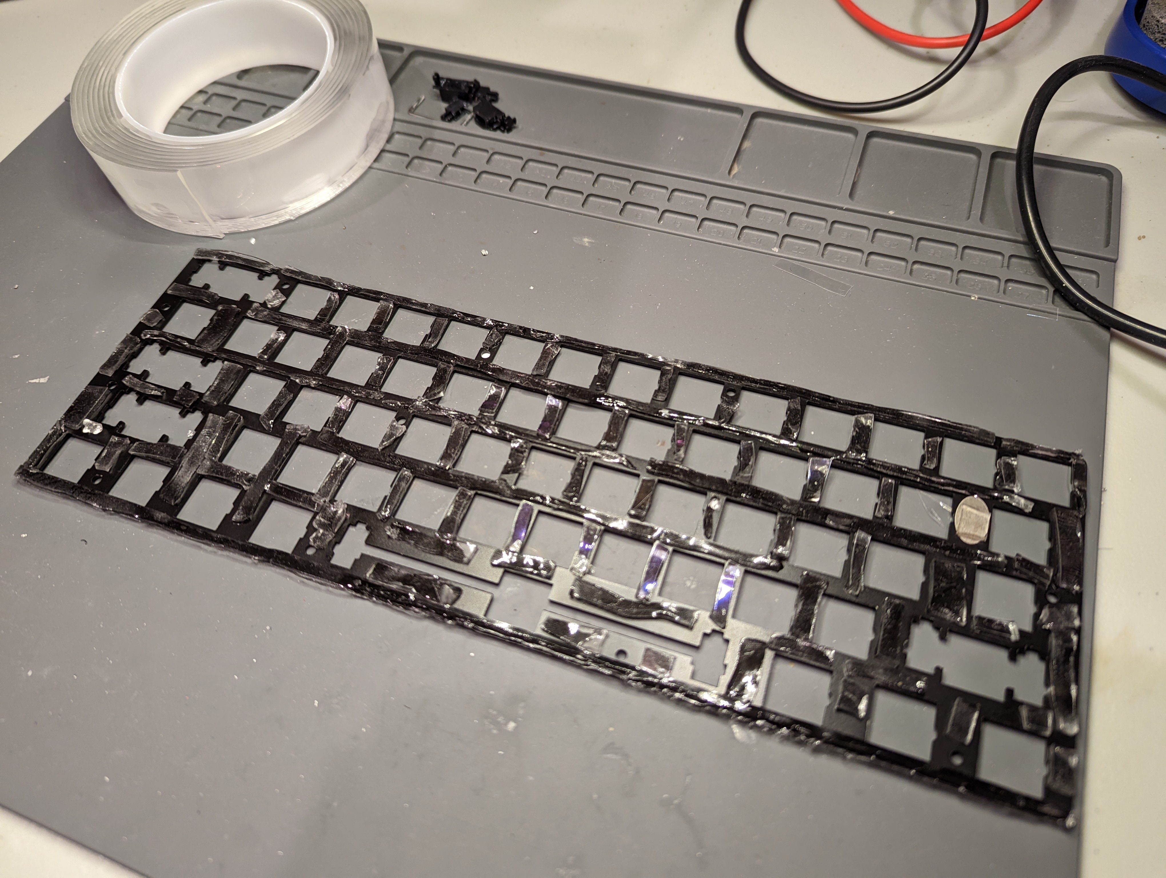
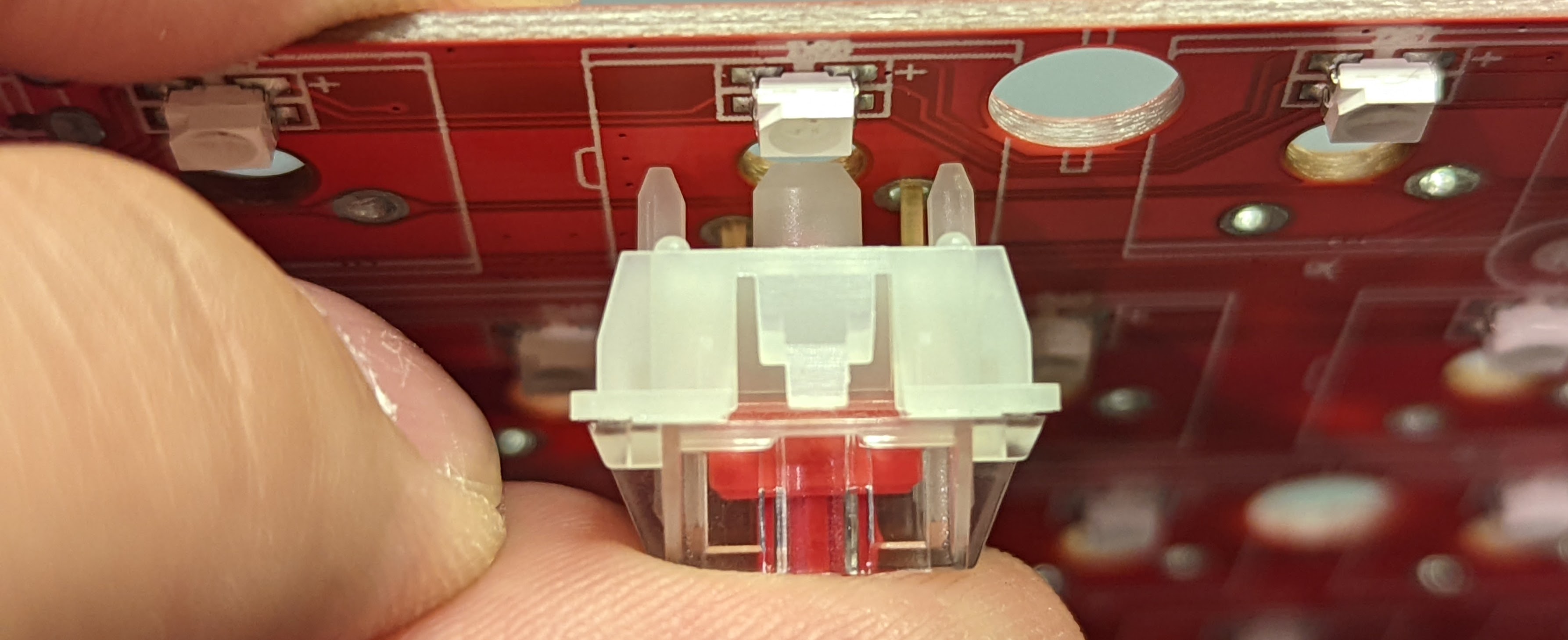
I also added a thin layer of PE foam between the PCB and the underside of the doublde-sided grippy tape. When I install the switches, their conductive pins will poke right through the PE foam, and make contact with their corresponding PCB sockets. You’ll see what I mean, once I get around to installing the switches.
Mod the Stabilizers
Nothing fancy here. Just some typical holee modding and lubing with Krytox 205G0.
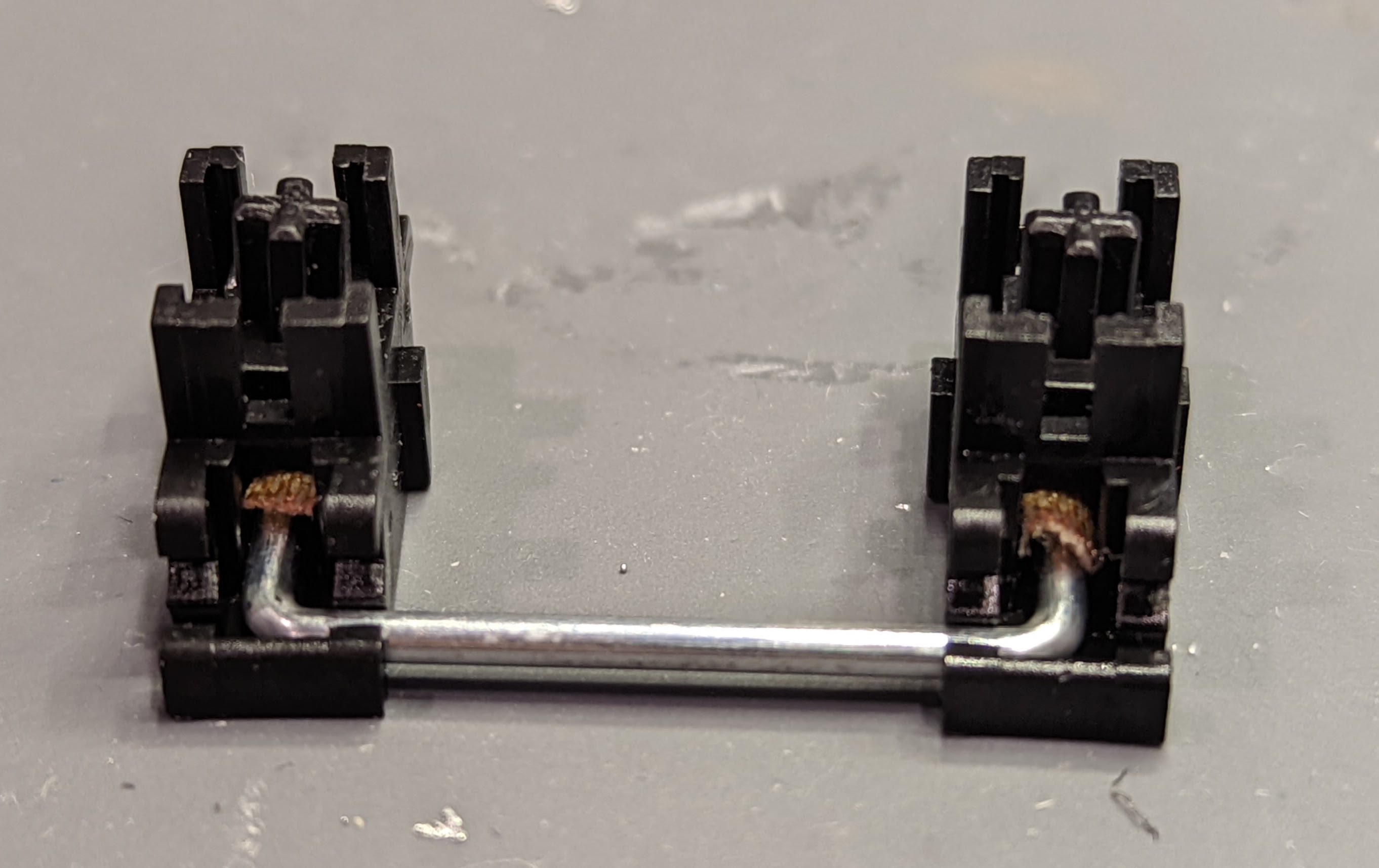
Like I mentioned above, the stabs are quite strange in that they clip onto the switchplate, rather than the PCB. This trait didn’t have too much effect on my modding, though, aside from the fact that the switch plate’s grippy tape ‘foam’ would sometimes interfere with the motion of the stabilizer bars. To get around the issue, I removed the grippy tape from the parts of the switch plate that were close to the stab bars.
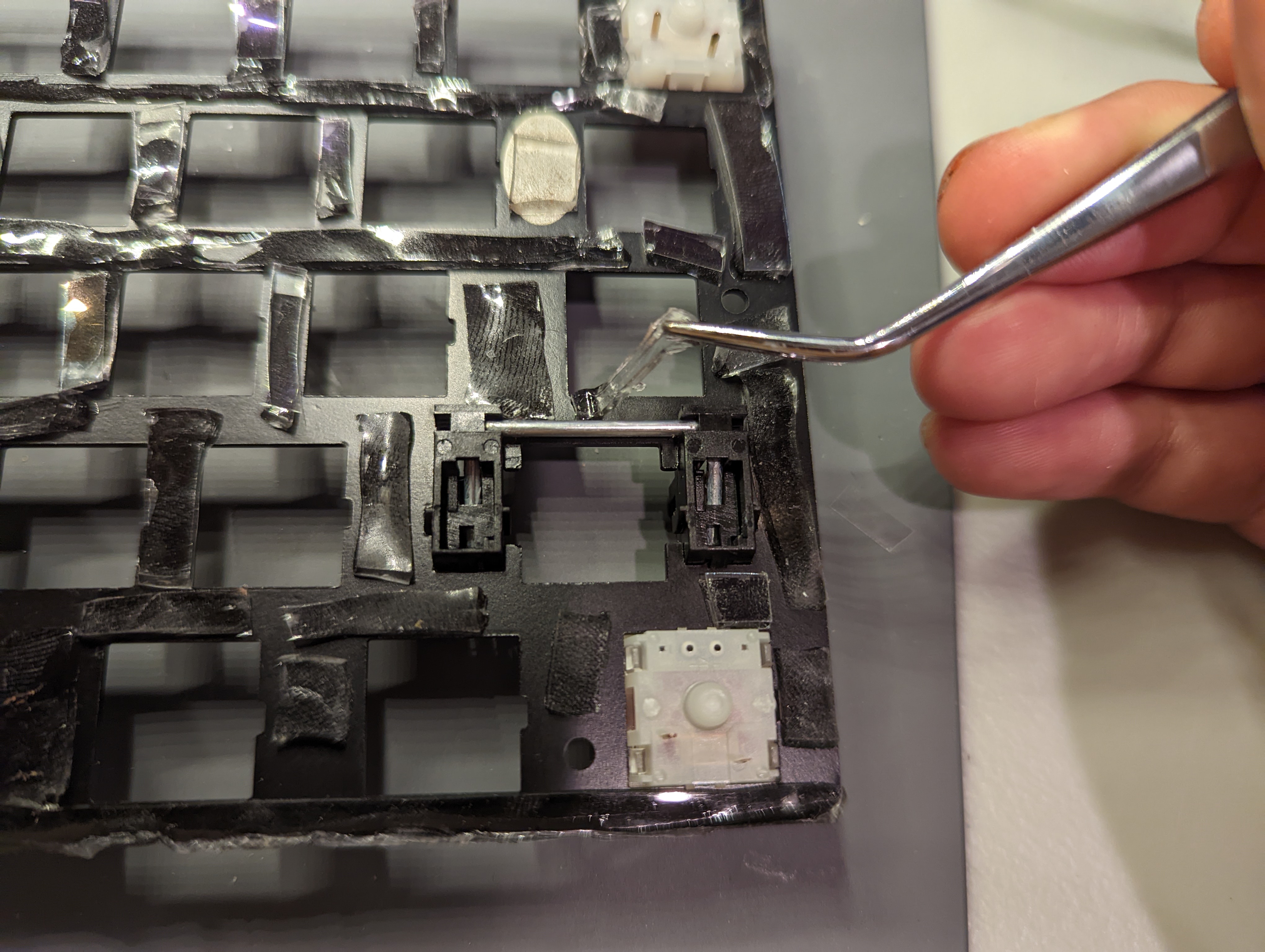
I then pressed the stabilizer-supported keys a bunch, to check that they were moving ok. Things seemed to be going not so bad, so far!
Add Decent Switches
During my disassembly process, I wound up getting rid of the crappy little hot-swap sockets (which were not Kailh-style, but were rather, low quality Mill Max-style). So the keyboard is now a solderable board, which I think is for the best, because the existing hot-swap sockets were already fraying, perhaps in part due to the shoddy PCB fabrication. Given that the keyboard is no longer hot-swap, I figured I should pick a decent set of switches, because they’ll probably be there a while.
I wound up picking the JWK Jwick Linear Reds (62 g), because they’re nice stock switches that don’t need to be lubed, and come at a really great price, at $0.23 USD / switch.
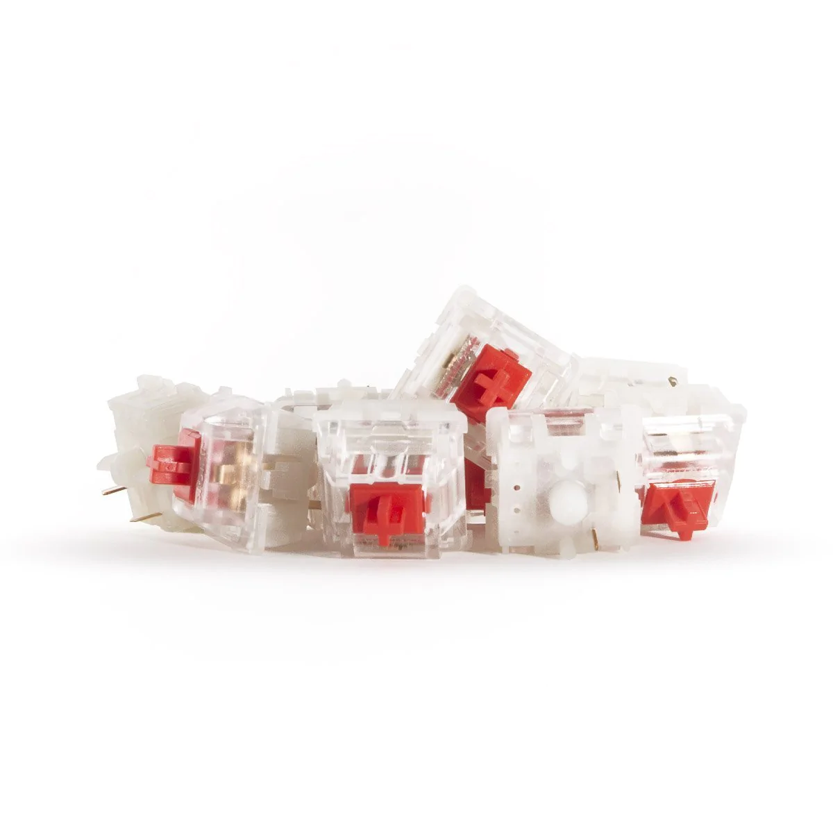
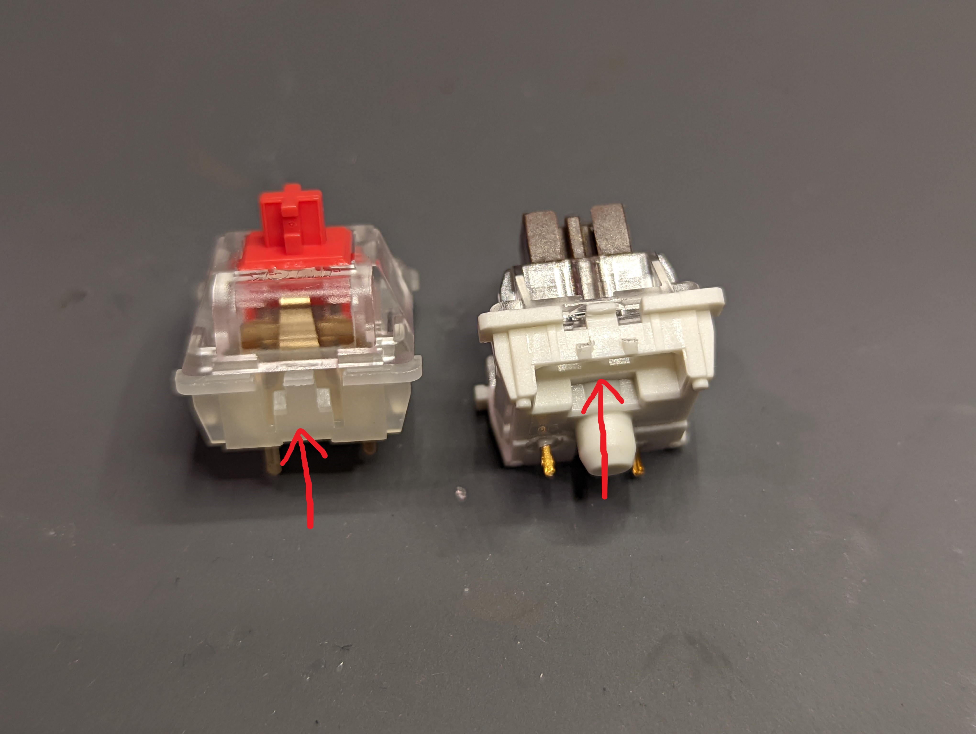
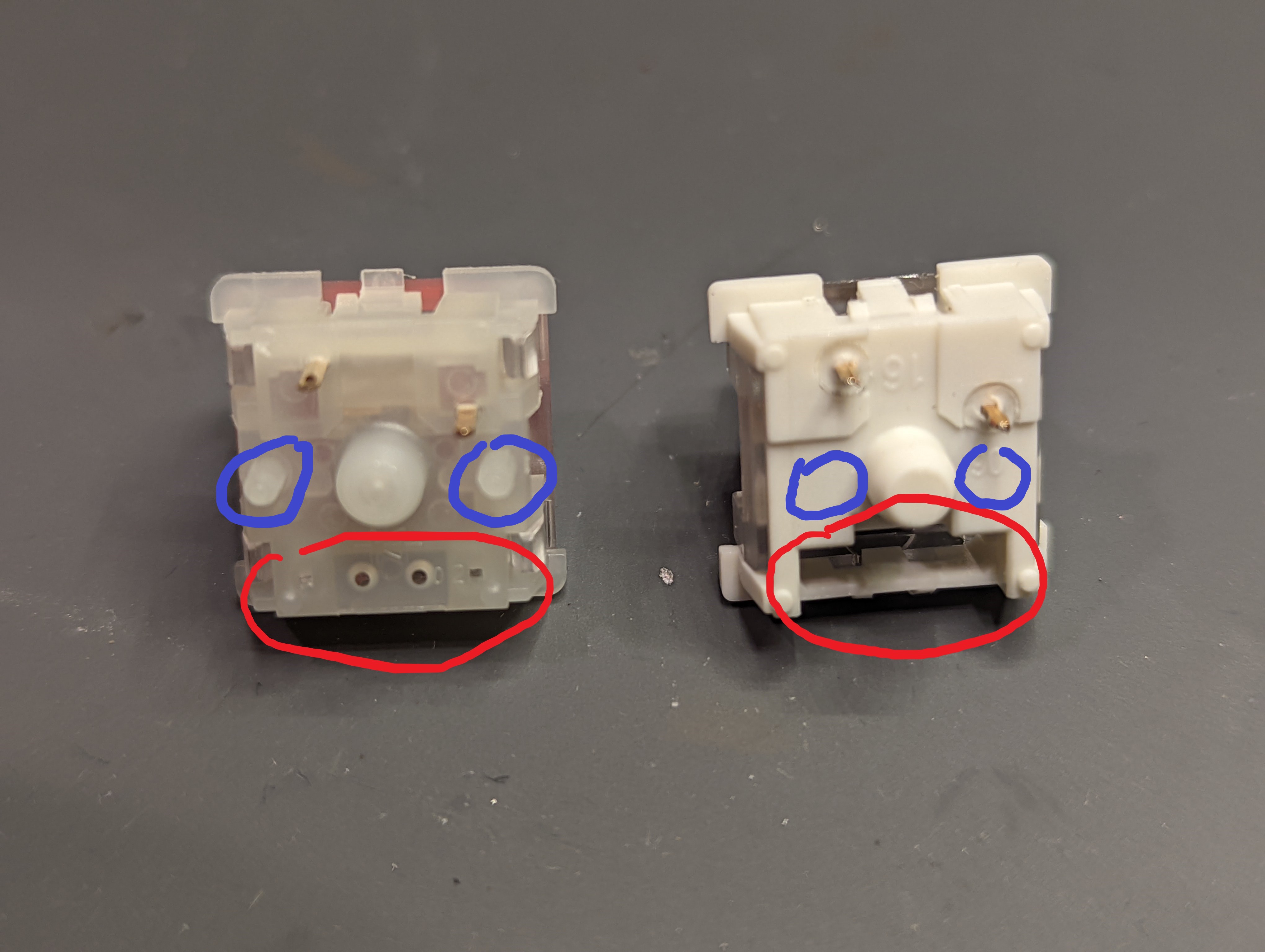
I realized after the switches came in, however, that the PCB accepted only 3-pin switches and not 5-pin switches (the term ‘pin’ here is kind of silly, because three of the ‘pins’ are just plastic protrusions that help secure the switch, but everyone in keyboard land just calls them ‘pins’). So I had to cut the two plastic legs off each Jwick, so that they effectively became 3-pin switches. The switches still weren’t fitting into the PCB though, and I realized that not only were the keyboard’s original Gateron Browns 3-pins, but they also possessed a large cavity at the back of the switch, so that the PCB’s RGB lights could shine behind each alpha key. The Jwiks did not have such a cavity, however, and so they refused to sit flush against the PCB, while the LEDs were still there.
Fortunately, my friends and I hate RGB, so I soldered those right off.
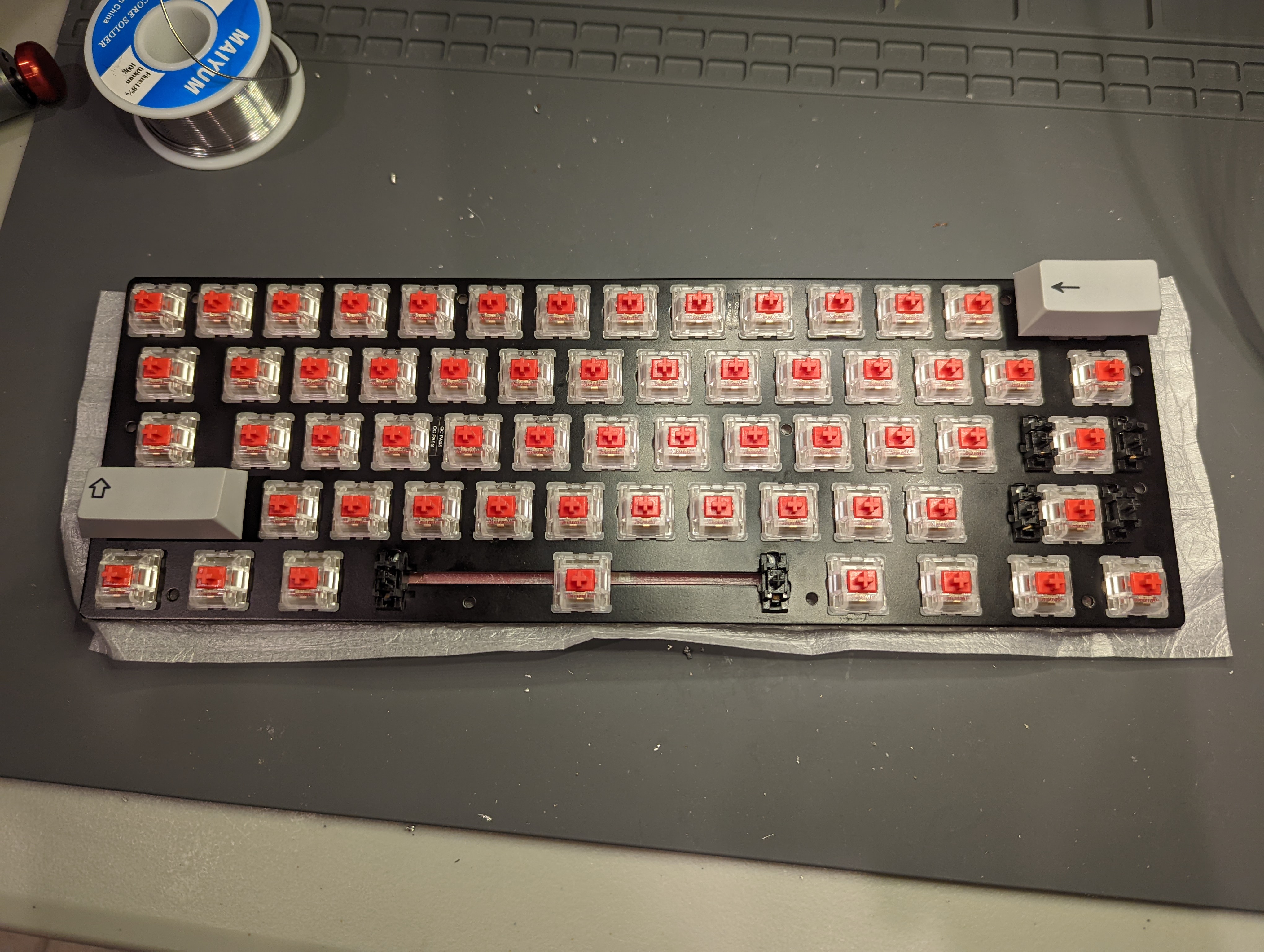
Finally, I was ready to install the switches and solder them in place. This part went very smoothly, and was quite relaxing.
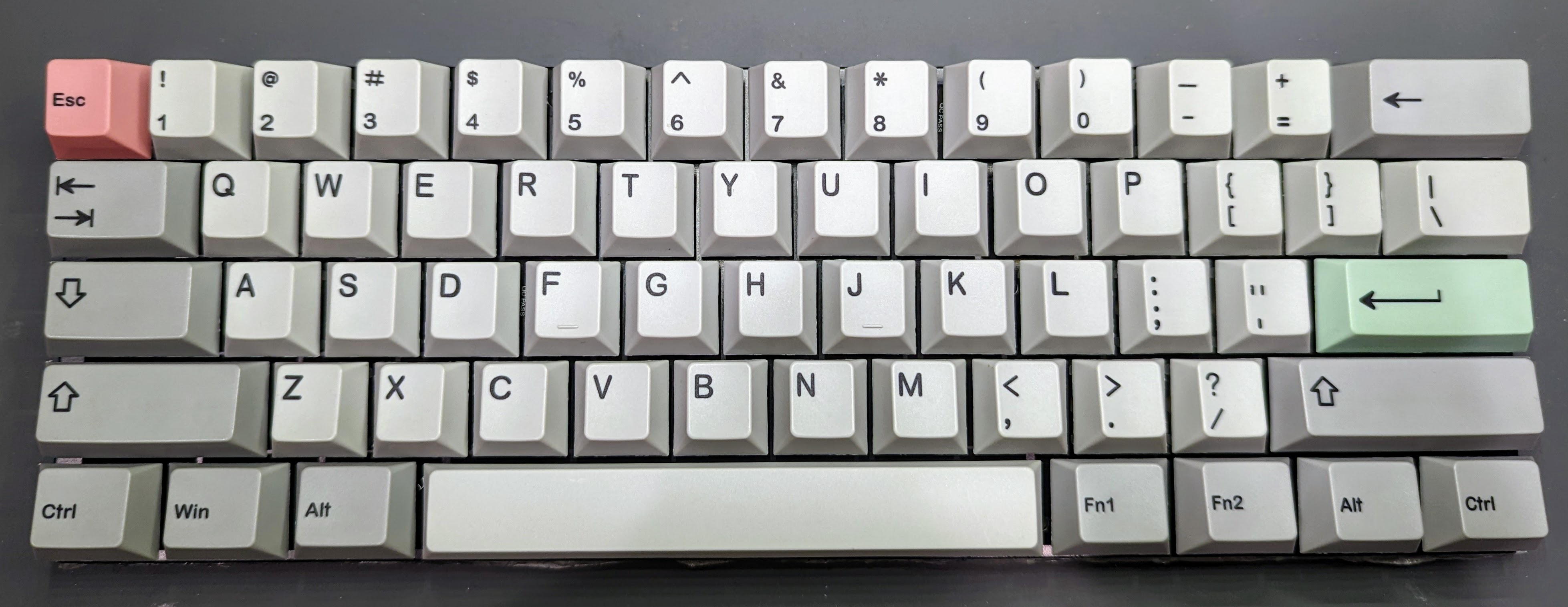
Then, I put on the keycaps. It’s almost impossible to mess this part up. I’m using some cheap Modern Dolch Light PBT clones I picked off of Amazon, some time ago.
With the switches and keycaps installed, I tried a few key presses, just to approximate for the typing feel (not so much the typing sound though, because I found that a representative acoustic test requires the keyboard to be mounted to its case). I was pretty happy with all the keys, except for the spacebar. It just felt kind of weak, given the lighter switch, even though the plastic of the keycaps were also pretty light—but I guess the spacebar is just a really big key. I swapped out the switch for a heavier Cherry MX Black.
Undo Mistakes
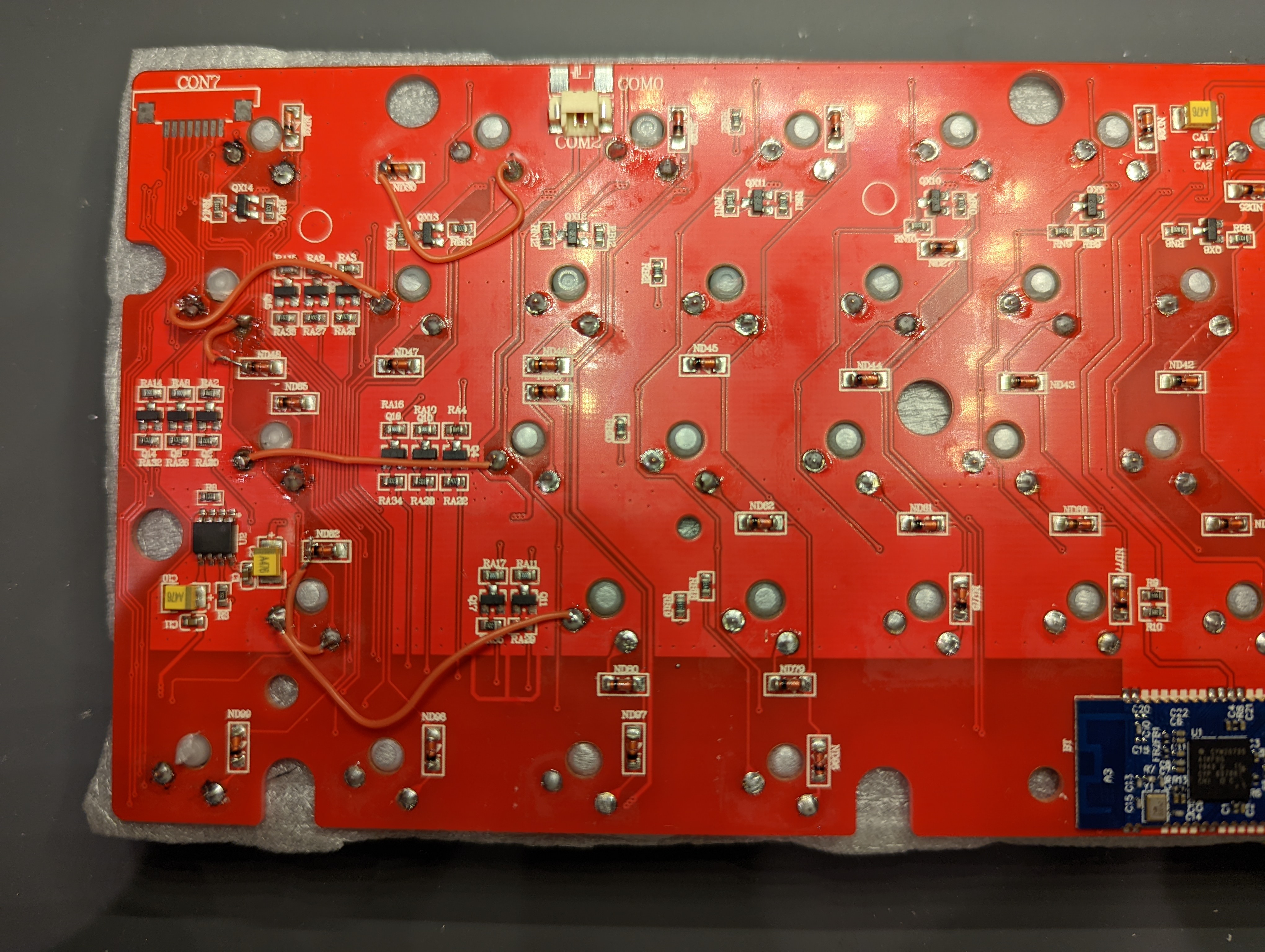
It turns out that when I was removing the cheap ‘hot-swap’ switch sockets during the disassembly process, I also removed the PCB’s copper tracing along certain switch footprints on the PCB. I shouldn’t have been too surprised about this wrinkle, given the general quality of the PCB, but I felt like it still could have been avoided. I took me more time than I’d like to admit to figure out the keyboard matrix circuit on this PCB, but I got it eventually, and I used some thin wires to re-establish the lost connections.
Remove Ugly Silkscreen Logo
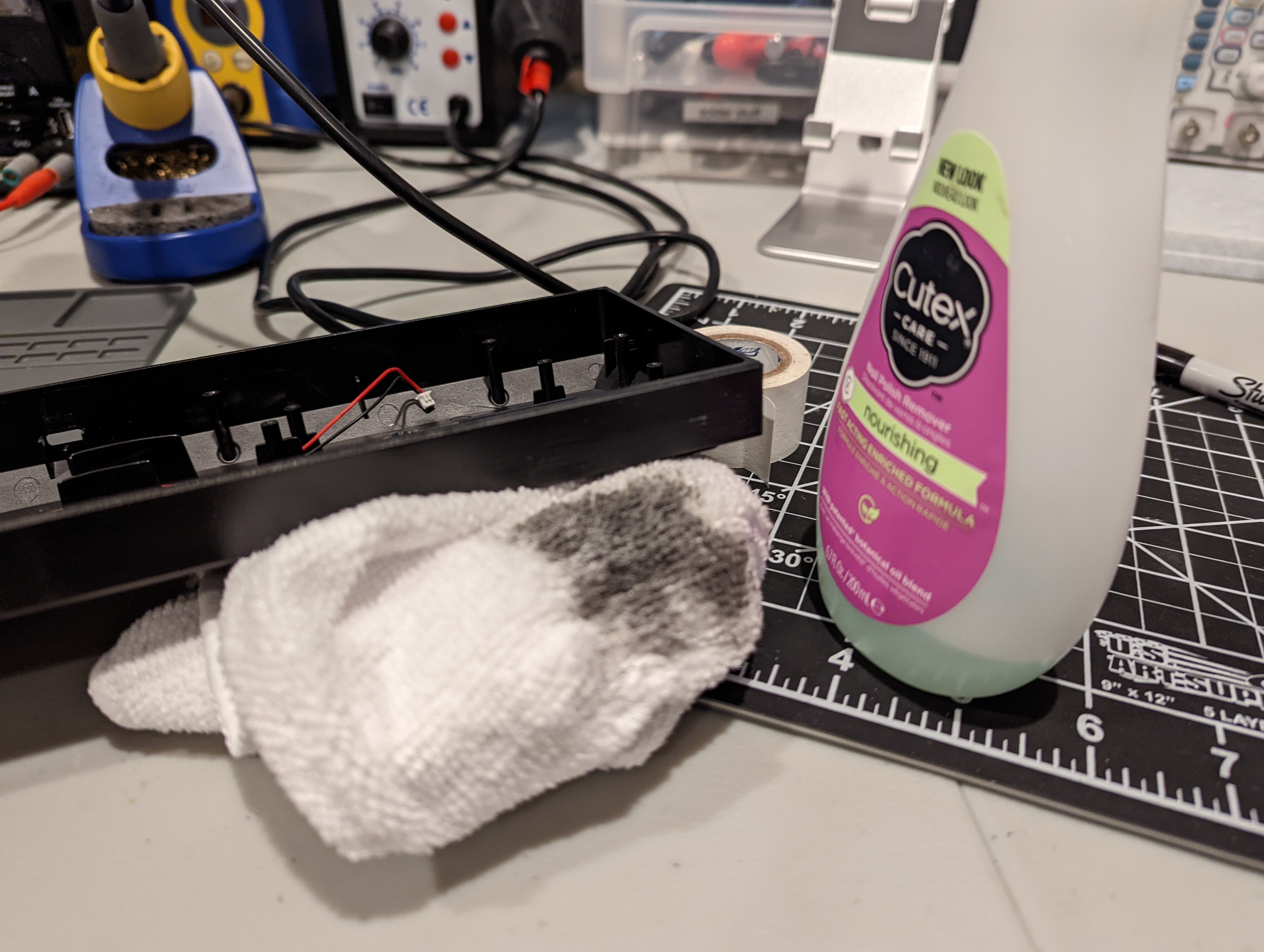
The keyboard’s original case has a really ugly logo that loudly reads “Velocifire” on its front. I got rid of it with some nail polish remover (acetone) and a lint-free cloth. The case is made of ABS plastic, so acetone also has a smoothing effect on the case.
Add a Gasket Mount
The way a keyboard is mounted is critical to its typing feel and sound. I think a fantastic and straightforward way of mounting a keyboard’s PCB and switch plate to the case is via a soft o-ring gasket. This strategy was made famous by the Bakeneko 60, and I’ve also used it myself for my ‘Planckeneko’ project. I got the idea of using an o-ring gasket mount as a part of a modding-on-the-cheap project from one of my fave keyboard YouTube channels, Keybored:
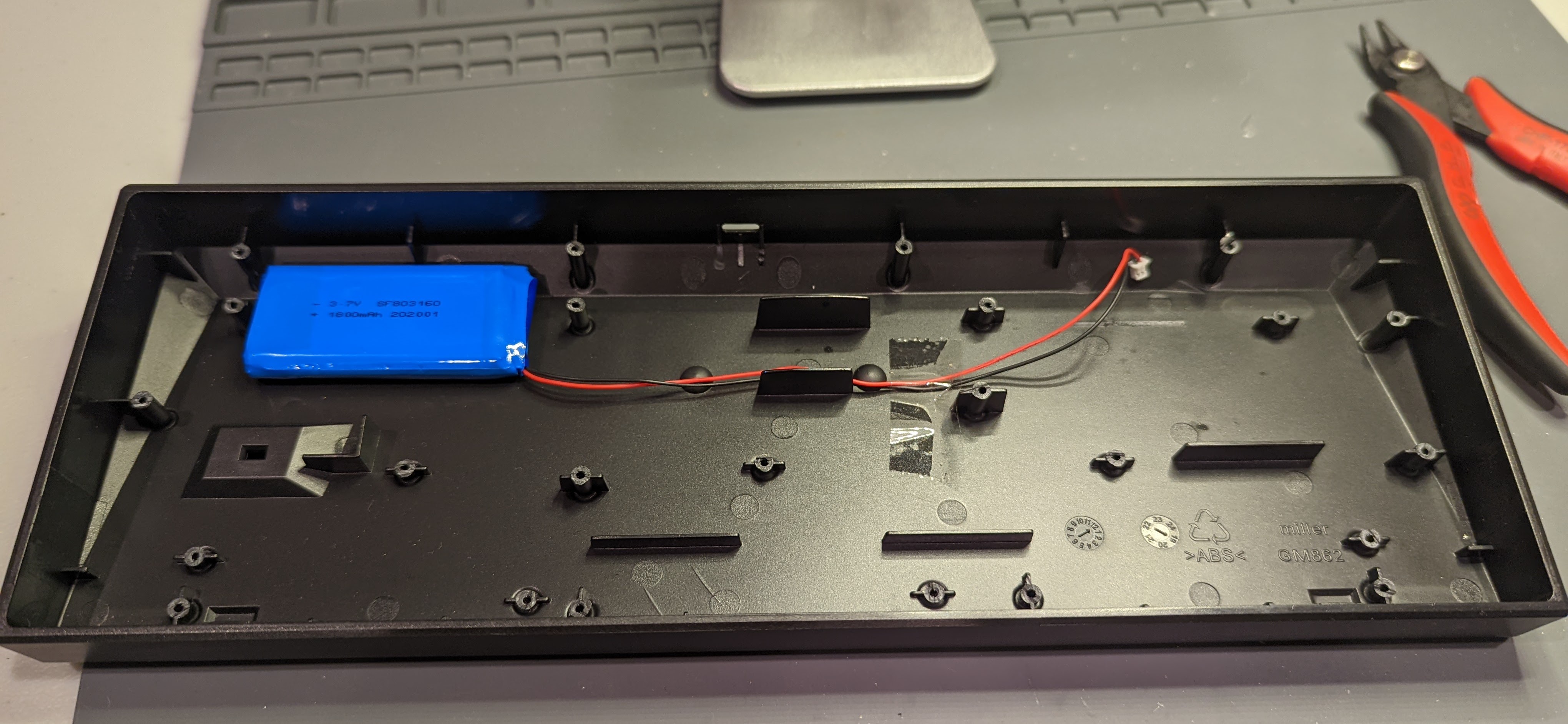
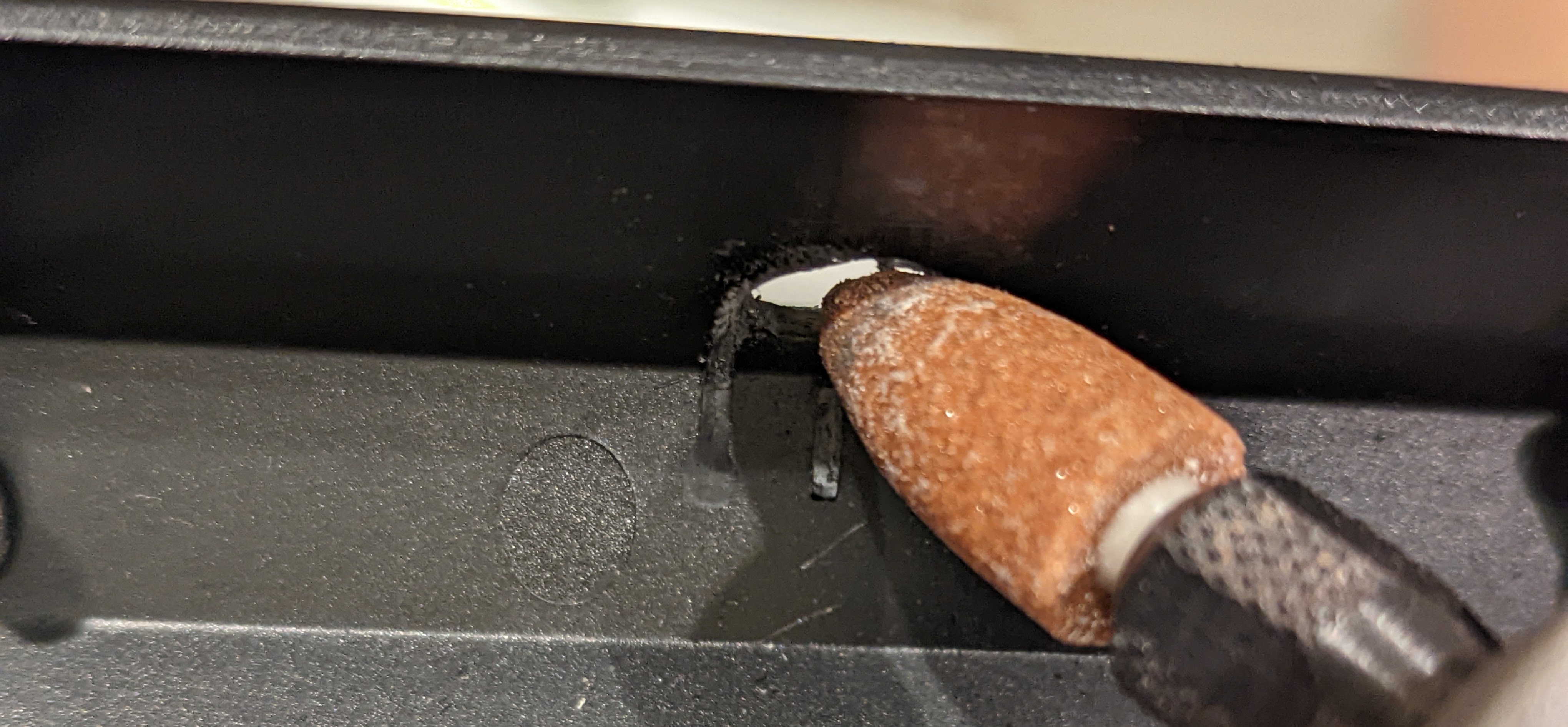
I think I’m going to take the same approach as the video, and saw off the original plastic standoff mounts, so that they no longer provide any mounting contacts, and all contacts are done via the gasket instead. There are a ton of integrated stand-offs on this keyboard case. I cut off all of them. I used some flush cutters to get rid of the stand-offs.
In the above Keybored video, the PCB had a daughterboard for the USB port, which is expected of most gasket-mounted keyboards. The logic to having daughterboards is that if the PCB is going to have some pliance for that soft typing feel, you don’t want the USB port cut-out on the case to prevent the PCB’s vertical flexibility. Without a daughterboard for the USB port, the case’s USB cutout would be on the main PCB, and it would be making a hard contact with the USB port, which would inhibit any vertical give. So the favoured solution is to separate the USB port onto a daughterboard.
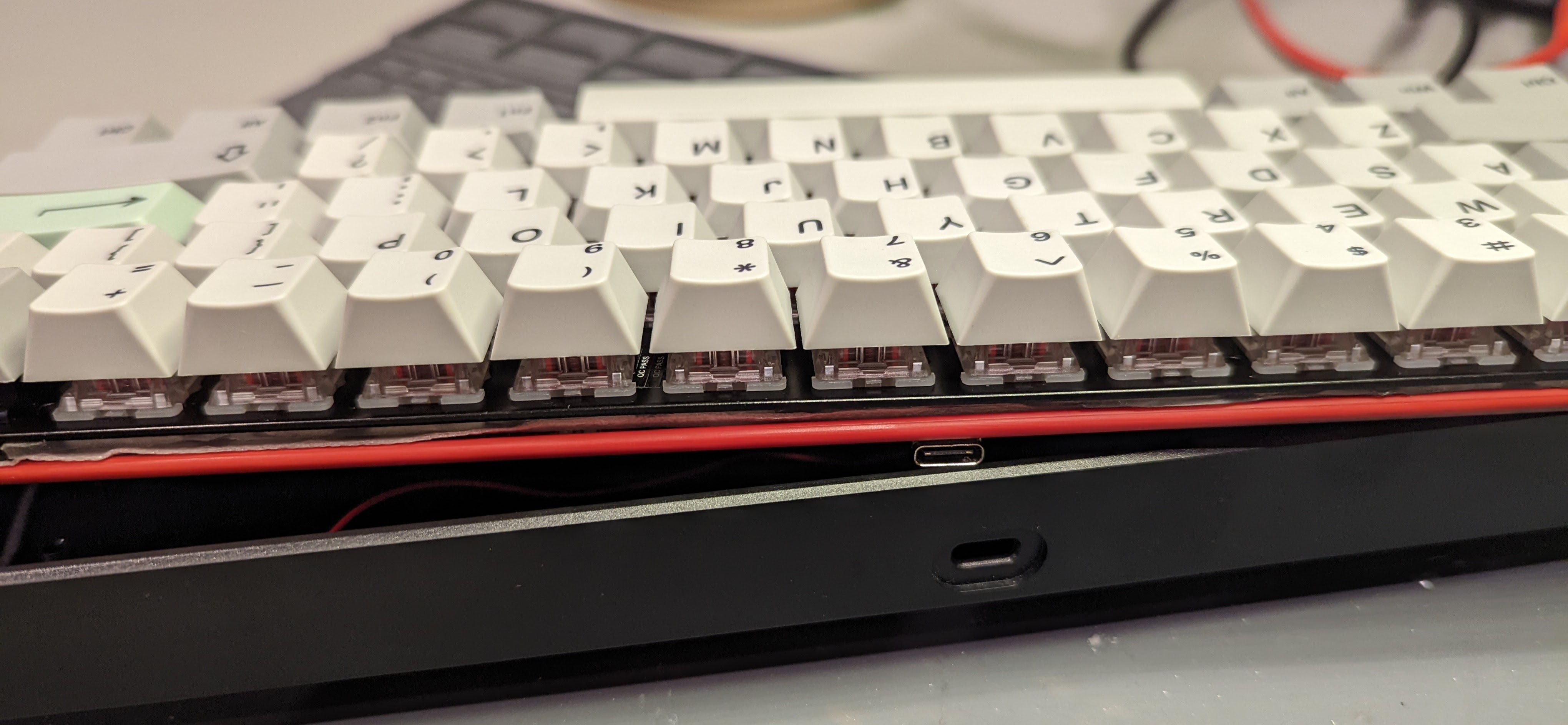
Alternatively, if not using a daughterboard, one could create space between the USB port and the USB cutout on the case. Some aesthetic purists might argue that there being such a buffer space between the USB port and the cutout might be a little ugly, but very popular and good-looking boards, such as the recent QK65, have successfully taken this approach1.
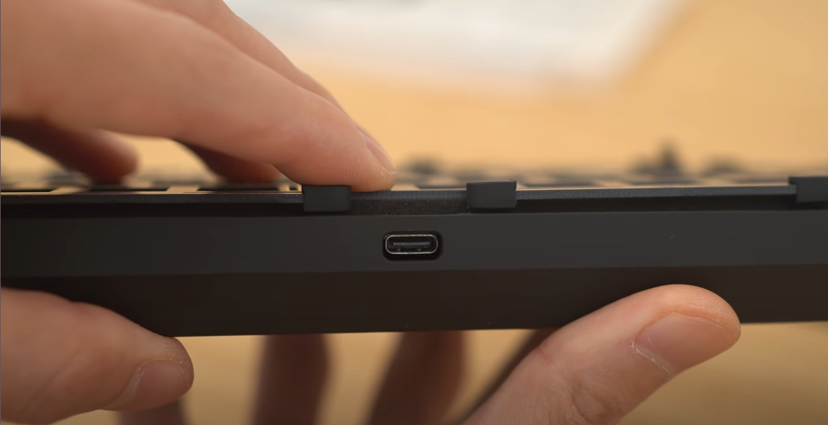
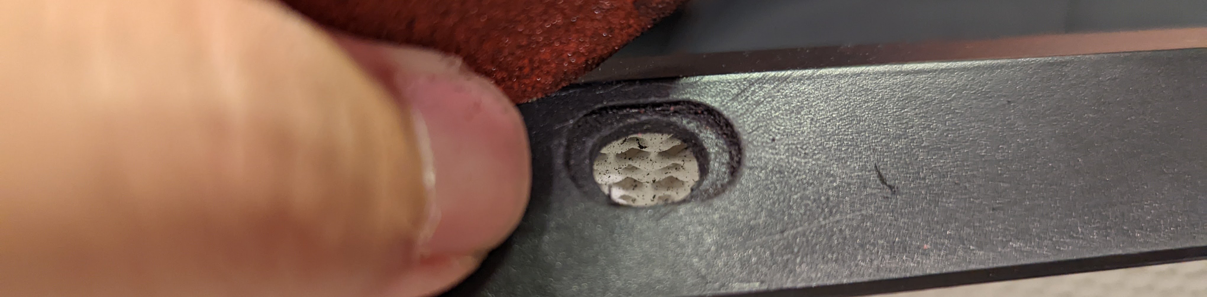
The PCB I’m working with isn’t very compatible with a daughterboard, so I opted to go down the QK65 route. I used a dremel to enlarge the USB port. I might have overdone it a bit, but I think it’s still fine, overall.
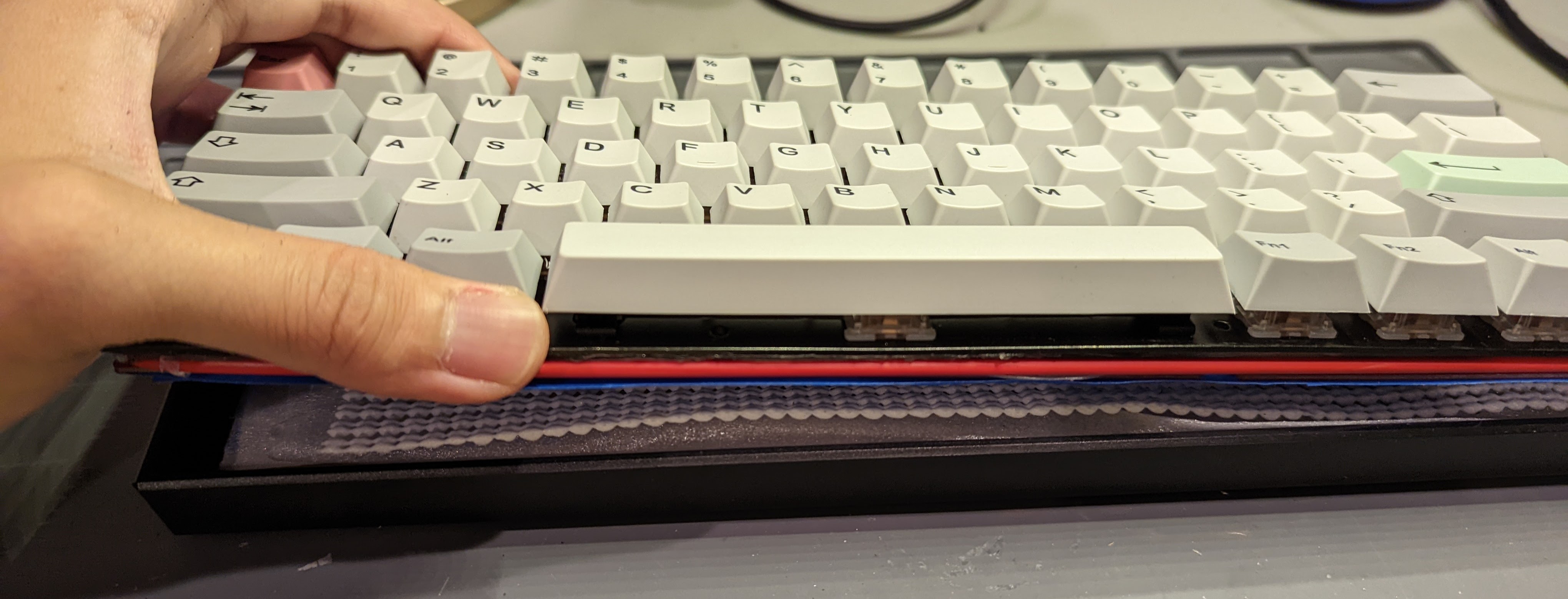
I then ordered the secret sauce: an o-ring gasket. I’m using the same o-ring gasket as the one for the original Baknekeko 60. I wrapped the o-ring around the PCB and switch plate, as is standard practice.
I found that the o-ring was squeezing out some of the sticky tape that I put on the underside of the switch plate. So I removed the sticky tape strips that were on the switch plate edges.
Tape Mod
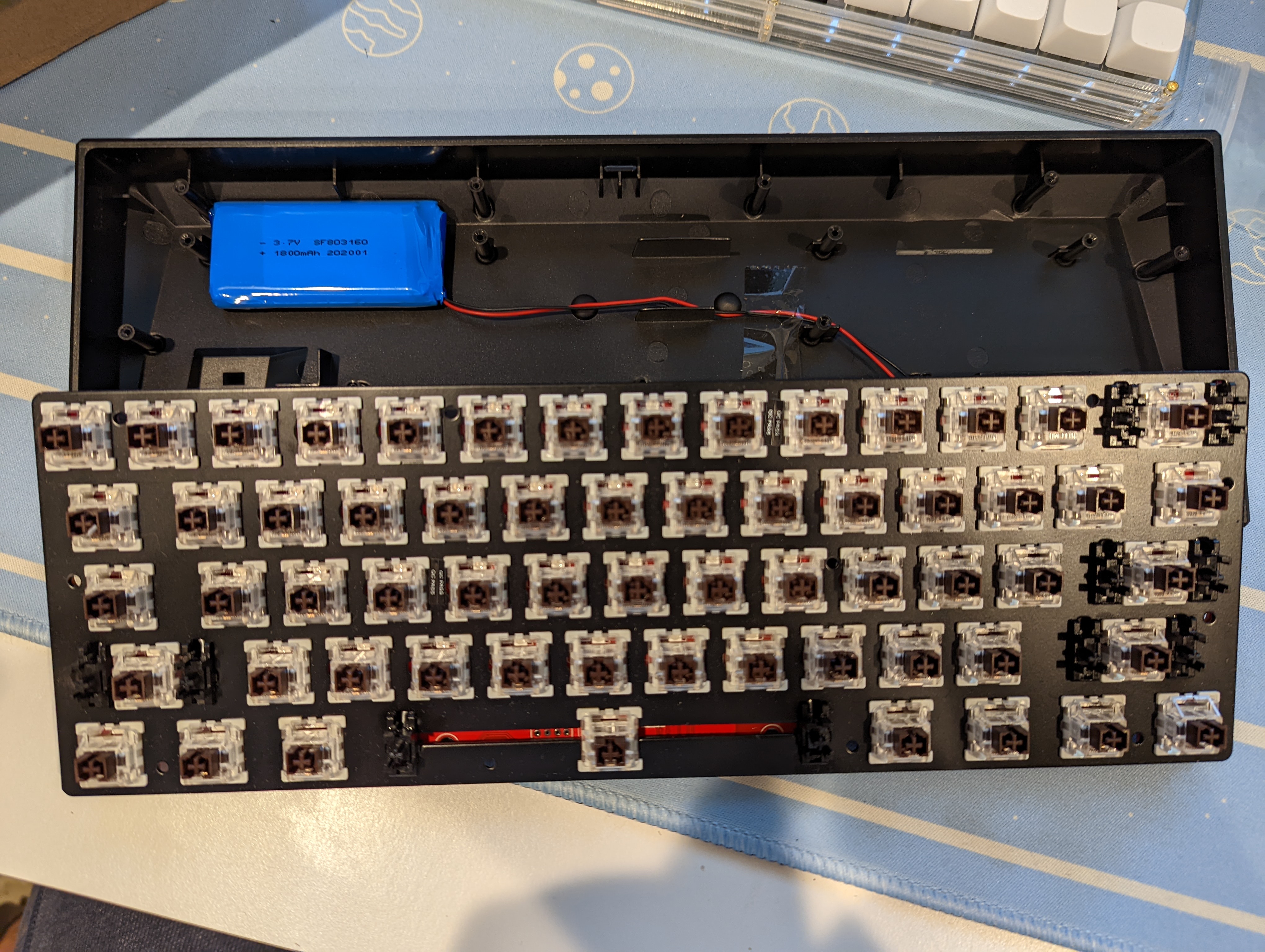
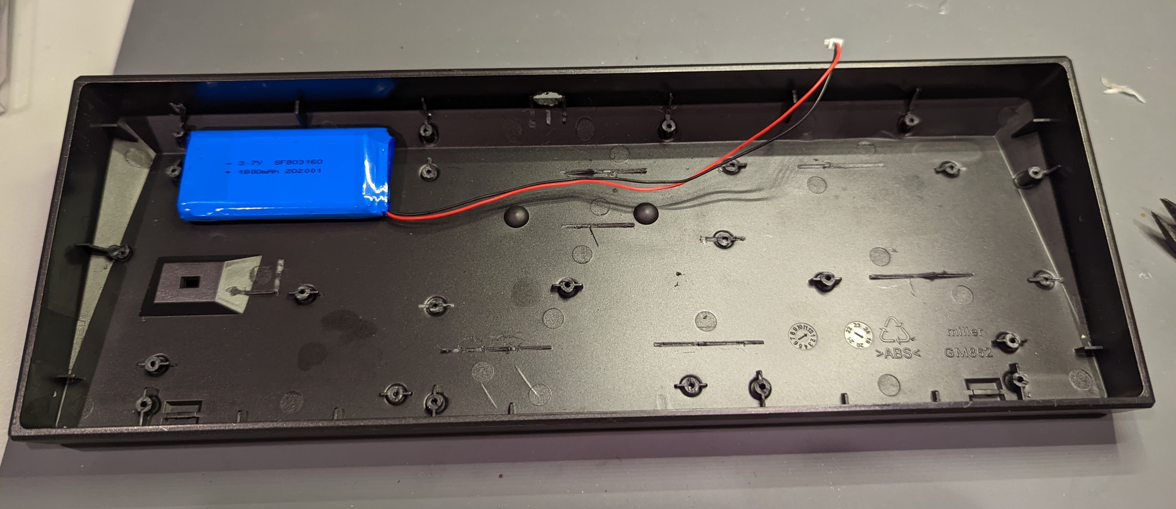
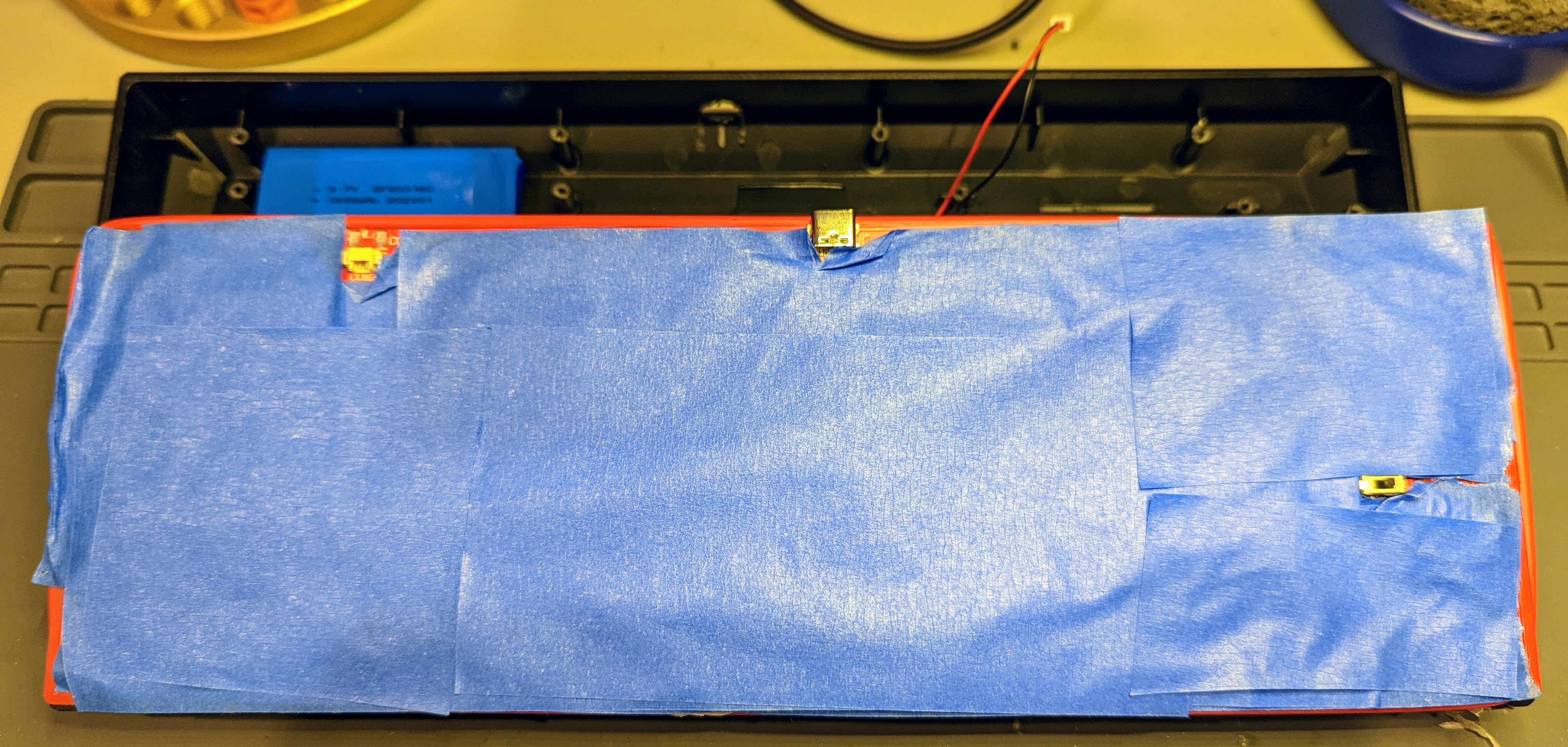
If not using a semi-flex PCB with lots of flex cutouts, I think it’s usually a good idea to do the popular ‘tape mod’, and tape the back of the PCB, preferably with the 3M ‘blue tape’. I used 3 layers, and I made sure to leave space for the battery power switch and the battery JST socket.
Case Foam and Finishing Hardware Touches
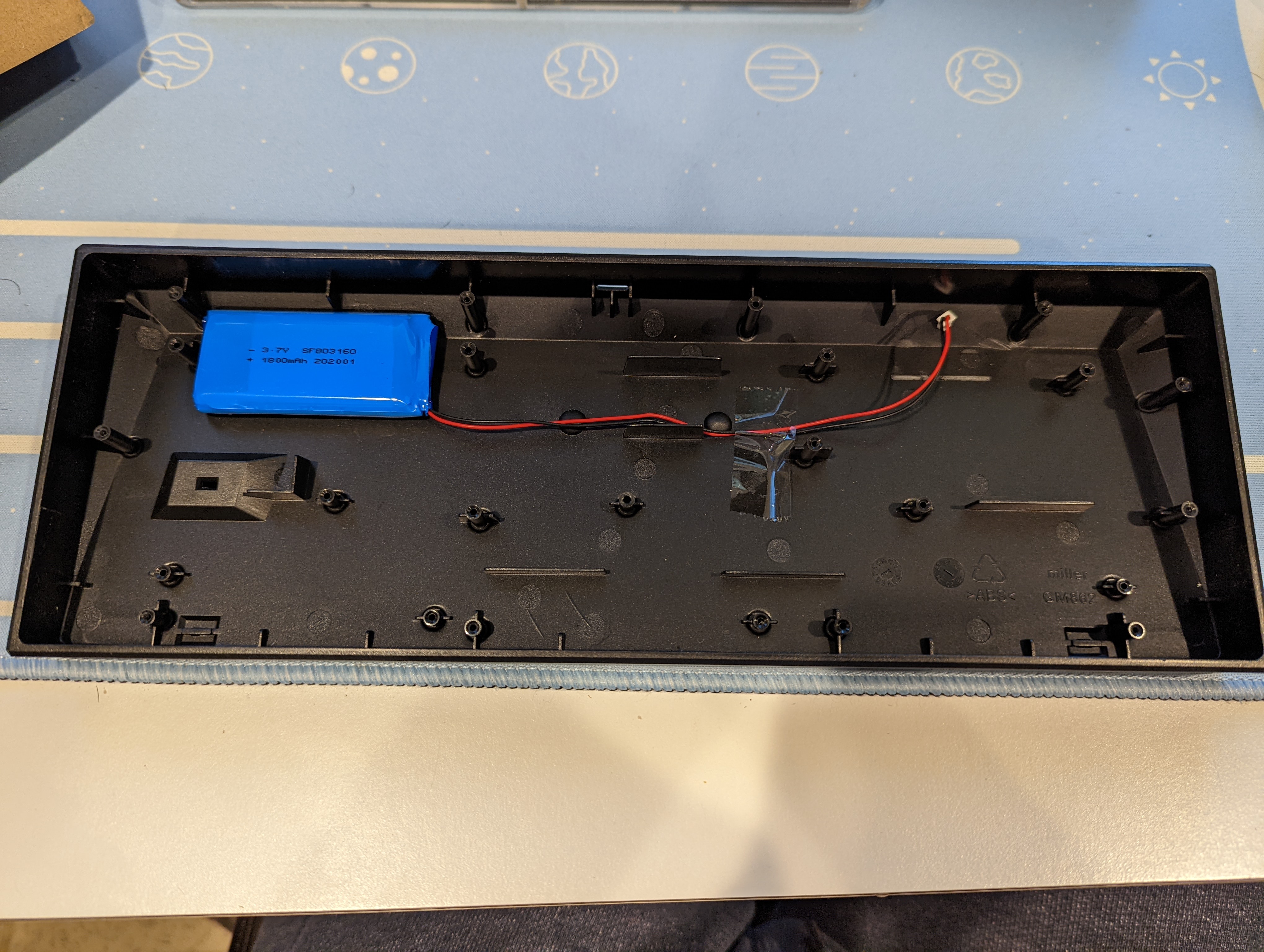
I really experimented with what foams to use for the case foam. I had a fair bit of space I got to work with, after I cut off all the excess plastic standoffs. I tried various combinations of car sound deadener, PE foam, and drawer liner. In the end, I took everything out, except for a single layer of the drawer liner, because that’s what I thought sounded best for this board!
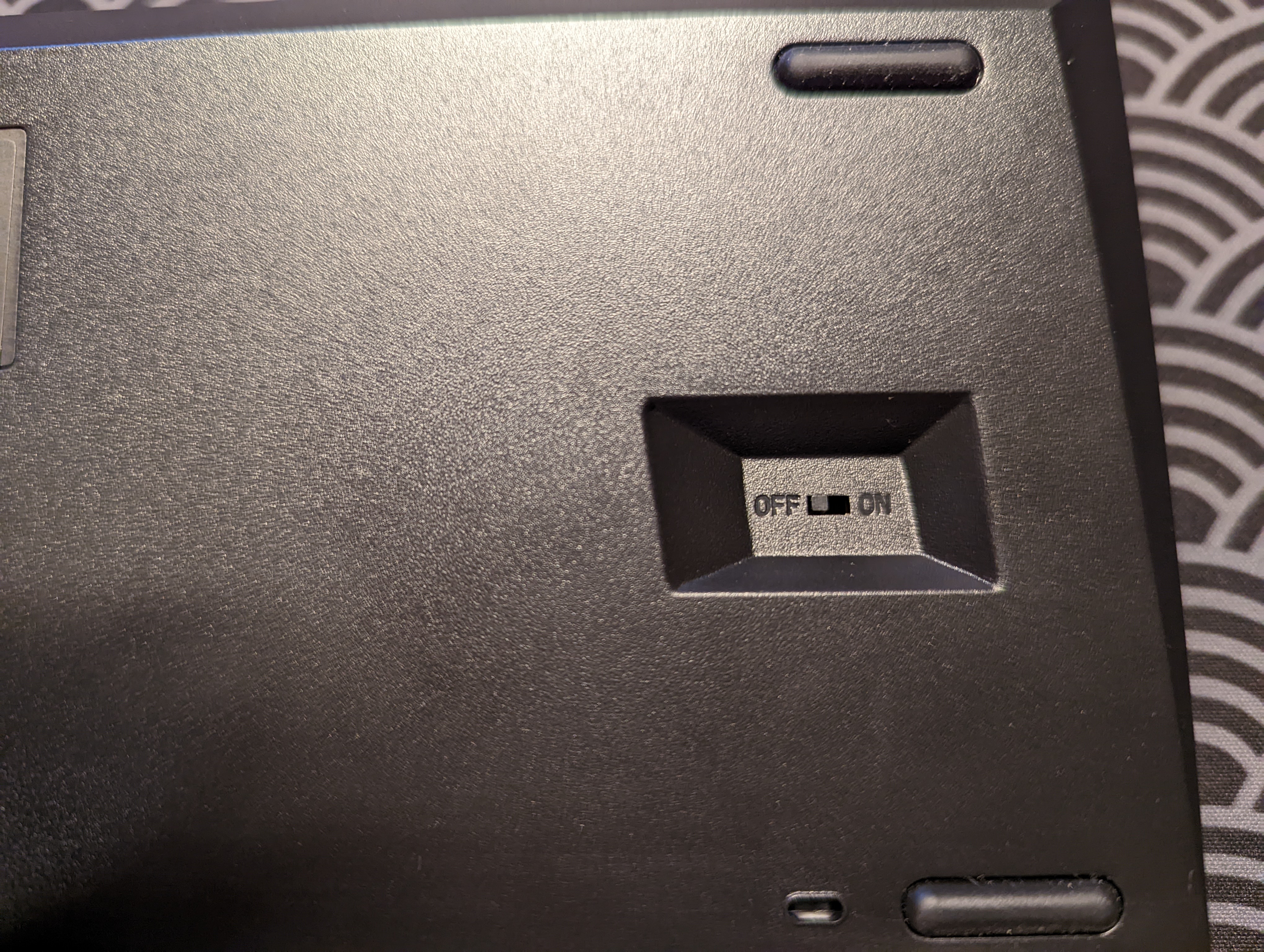
I was also relieved to see that the toggle switch that controls the battery power (this keyboard is Bluetooth-capable) was still able to jut out of its cut-out without a problem! ![]()
Make it QMK-Programmable (a fail  )
)
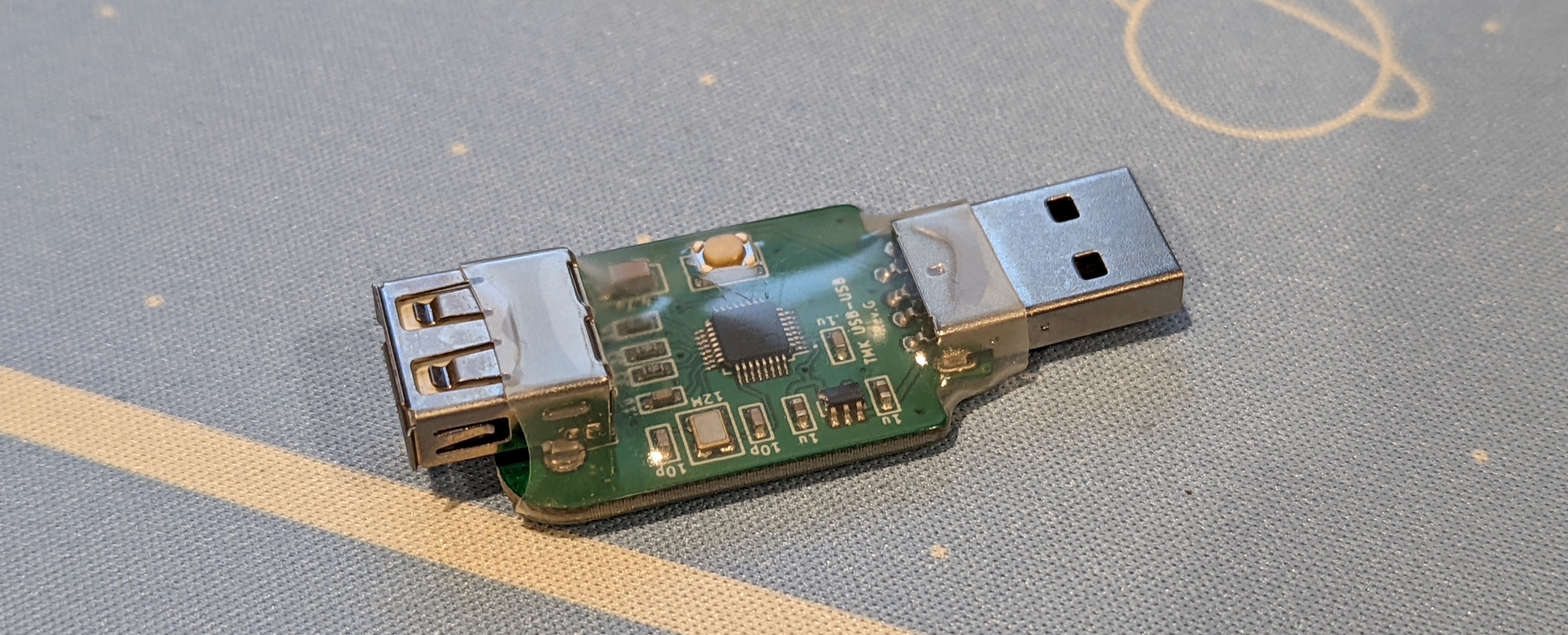
I own a Hasu USB-USB converter, from back when I first got started in the hobby. I don’t use it anymore, because I don’t like boards that aren’t natively programmable, but I think it might just the thing for this modding project. I recall my friends mentioning how confusing it is to access the arrow keys with the Velocifire’s default configuration, so I’m hoping this adaptor will change all that.
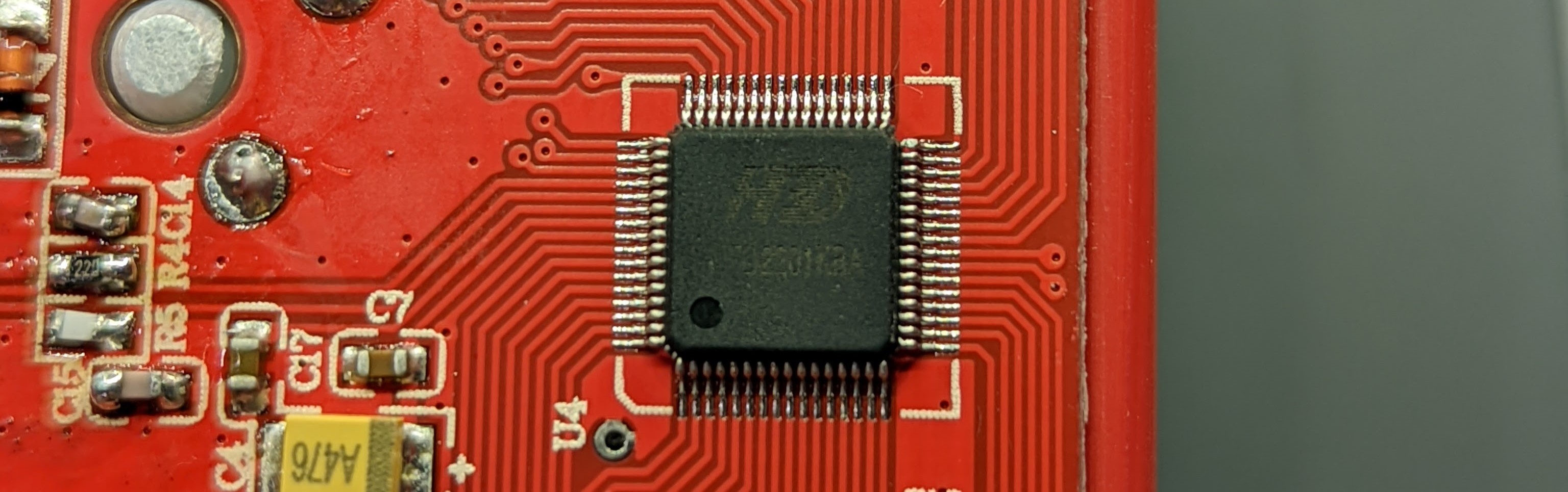
Unfortunately, the hope was misplaced. I knew that not all keyboards would be compatible with the Hasu USB-USB controller. The Hasu USB-USB controller worked great with various other boards I own, but failed to work with the Velocifire. I tried to get a closer look at the µC the keyboard uses, just for my own curiousity, but it was really hard to make out. It didn’t actually matter anyway. It was just a little disappointing that I couldn’t QMK-ify my friends’ keyboard ![]() .
.
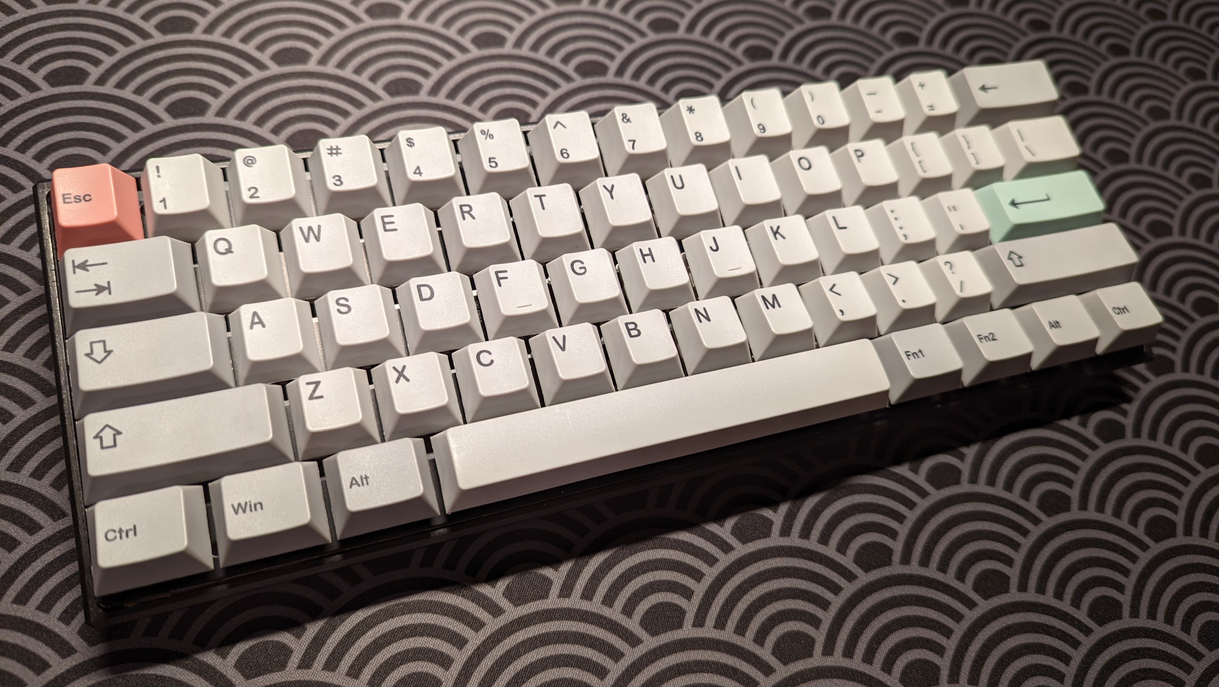
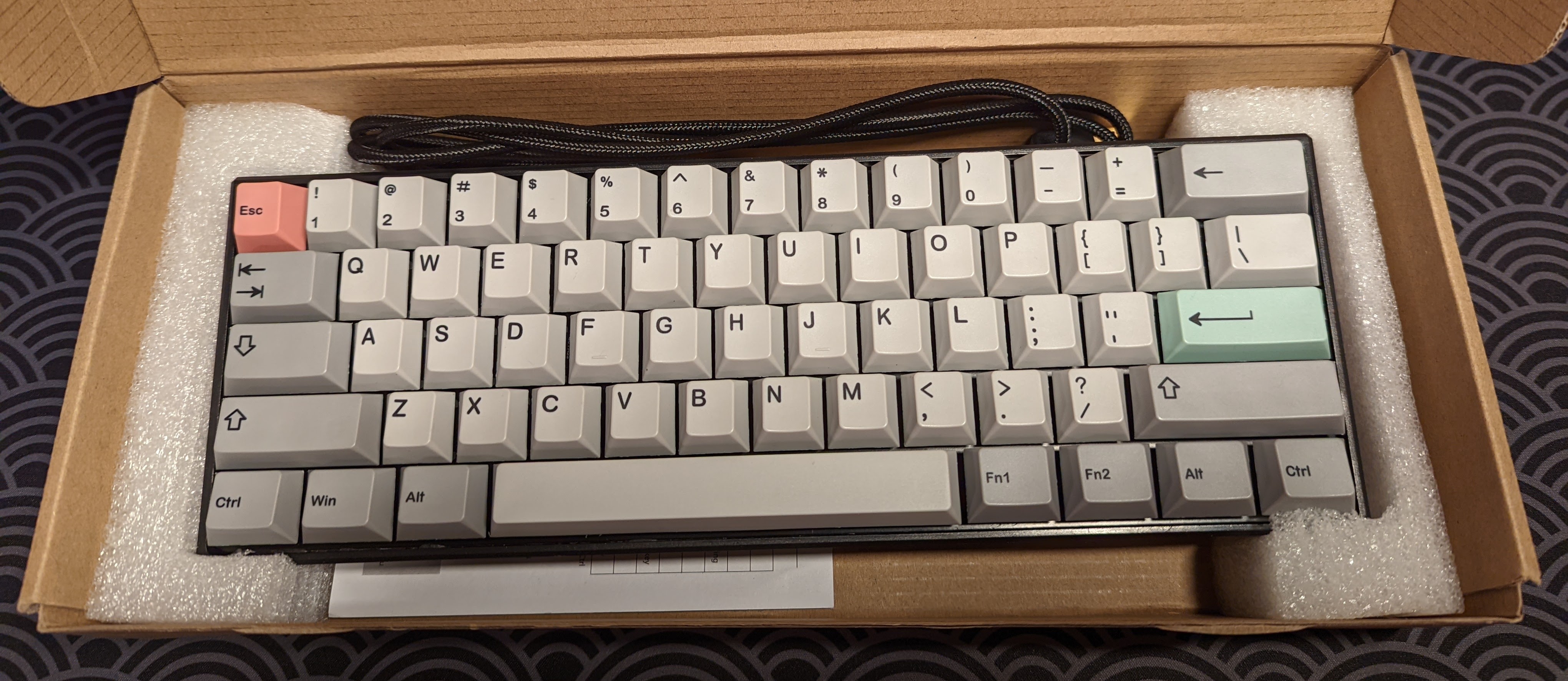
End Result
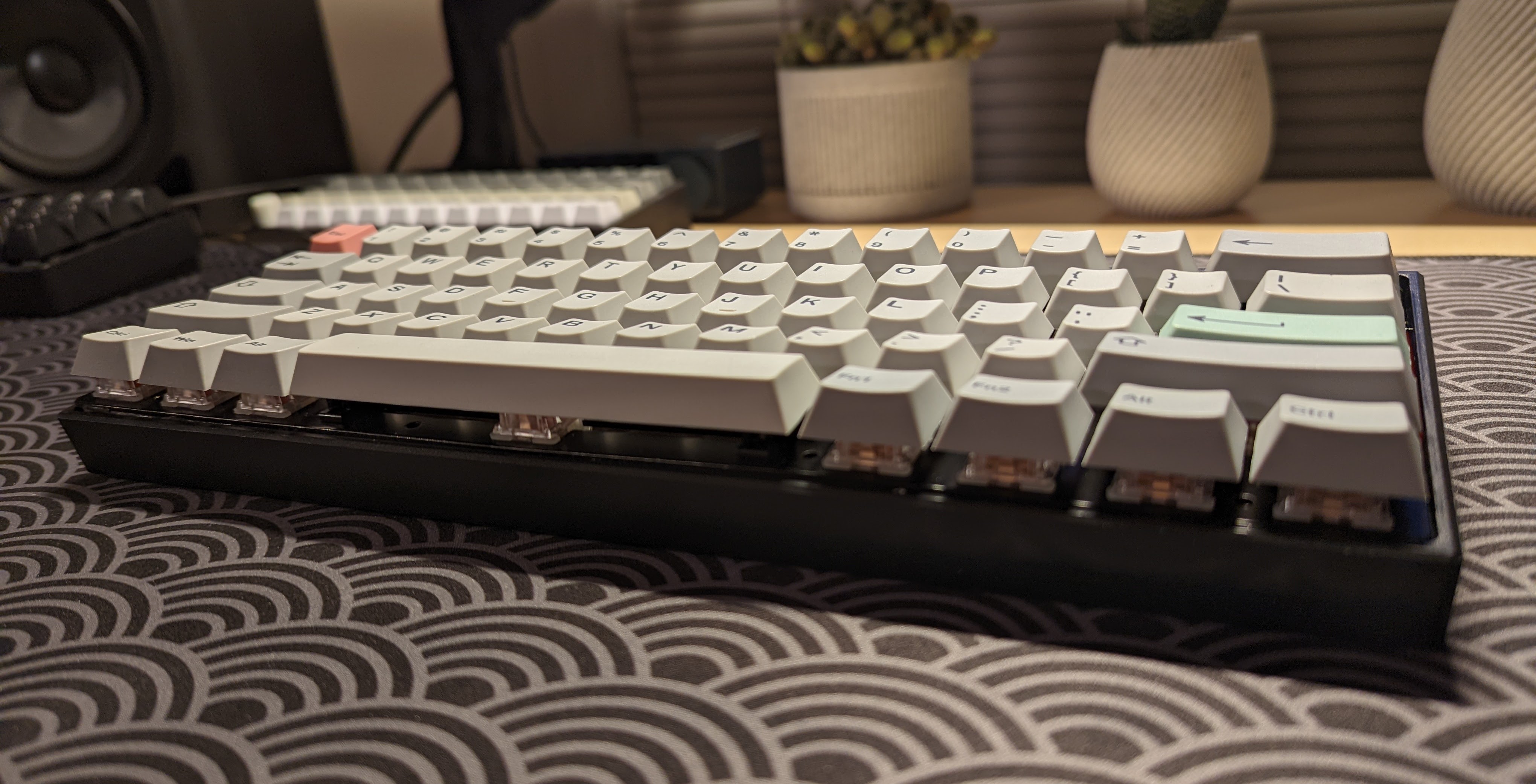
In the end, I was pretty happy with the result! I thought it looked pretty good, and the typing sound and feel is vastly improved from before. Here are a few photos of the end result!
I’m hoping to build a microphone soon, which I’ll be able to use to make a decent keyboard typing test. I’ll then update this blog post with the recording!