In this post, I document my build of a wireless version of the popular Corne split keyboard. I found this post to be very helpful, while I was building my wireless Corne. I talk about the changes I made to the original Corne keyboard, and the changes I wish I had made, if I was doing this build again.
Electronics
Most of my parts come from boardsource.xyz. The only parts I did not get from them are the case, the Mill-Max sockets and pins, and the SPDT slide switches. Most of the soldering in this build is SMD, and so I highly recommend using solder paste and a hot air soldering gun. Angled tweezers help a lot too. Only the µCs are soldered with a soldering iron.
-
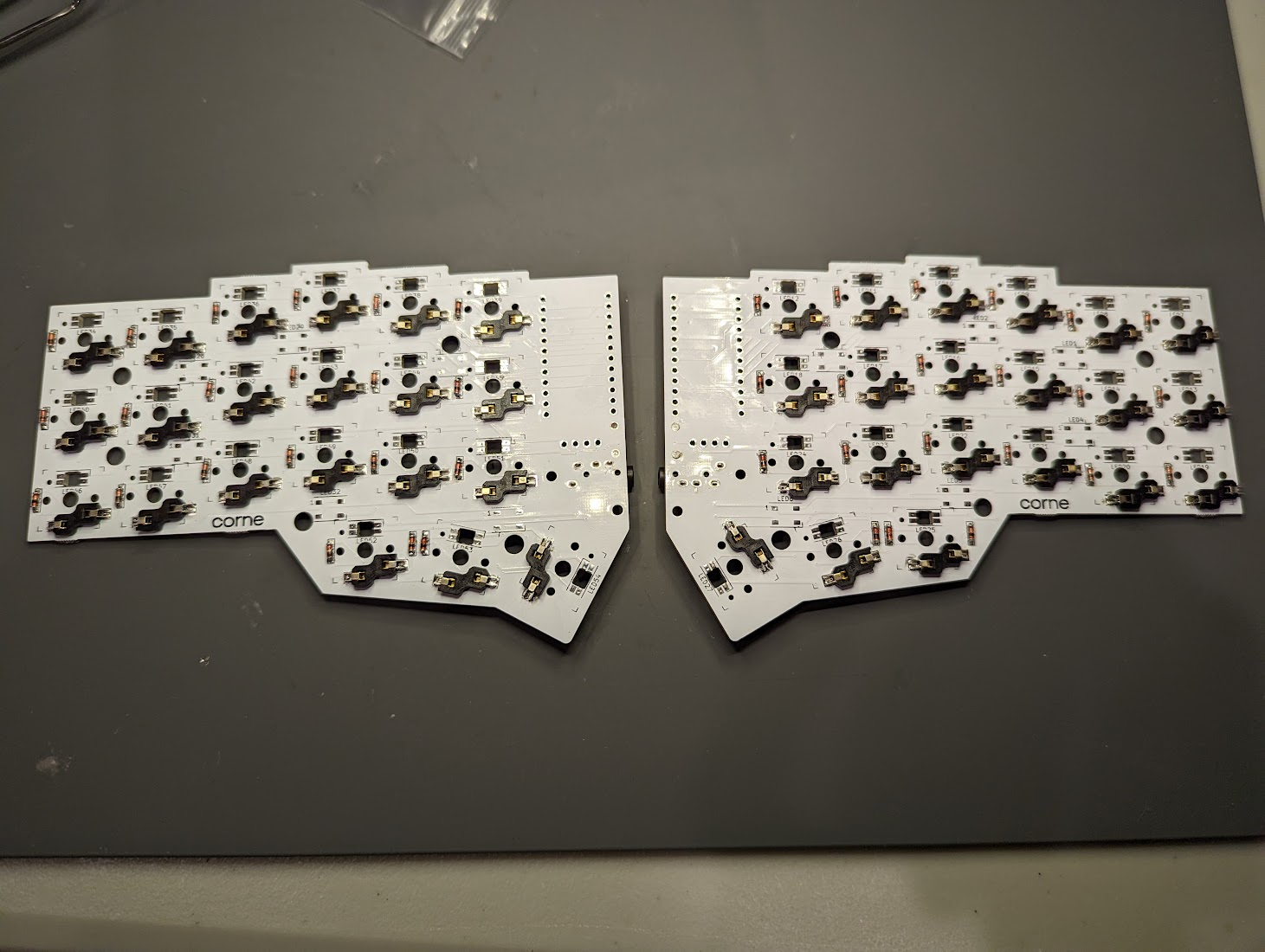
Solder the diodes. It’s not so bad, but the ones that came from Boardsource are cylindrical, and tend to roll. The pieces tend to more or less fall into places once heat is added to the solder paste.
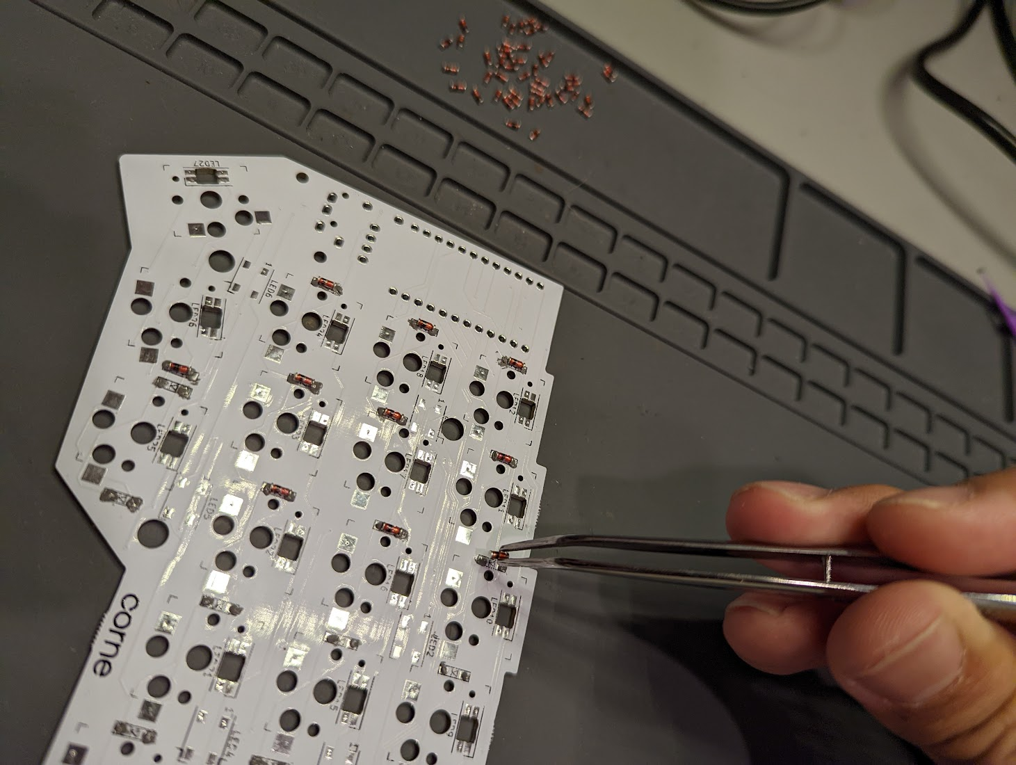
I apply the solder paste first with a syringe, and then I stick the diodes on. I then blast it with the hot air solder gun, and things more or less work out! Sometimes I have to use the tweezers to hold the diodes in place, so they don’t roll around. -
Solder the hot swap choc switches. Add solder paste onto all the pads, and then press in the choc switches. They should press in with a fairly snug fit. Then use the heat gun to melt the solder paste onto the hot swap pads.
-
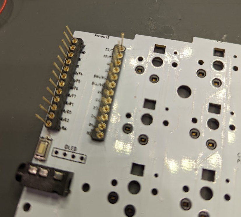
Solder the low-profile Mill-Max sockets. I got these sockets from Digikey (ED5624-ND). I soldered them onto the PCB with a regular soldering iron and a roll of flux-core solder.
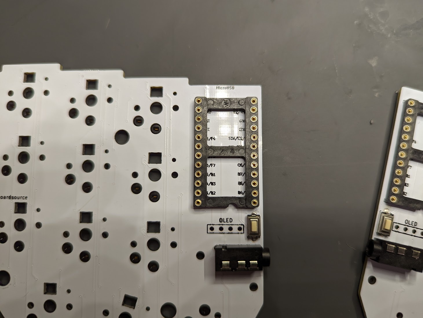
There’s a TRRS jack in this photo, because I was absent-mindedly assembling things. But because I’m doing a wireless build, I removed the TRRS jack later. -
Add the Mill-Max pins. Alternatively, you can use the leftover legs of through-hole diodes that are common for a lot of keyboard builds. But I think the Mill-Max pins are a lot better, just because they’re so much sturider. When adding the Mill-Max pins, it helps to use some needle-nose pliers to hold the pins, and then push them into the sockets.
-
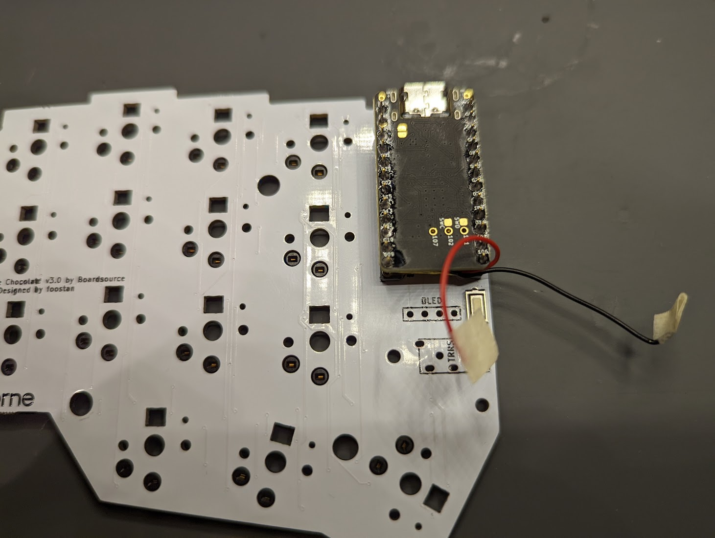
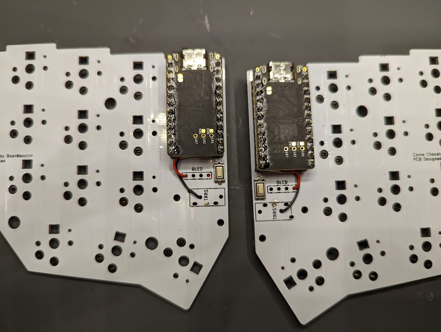
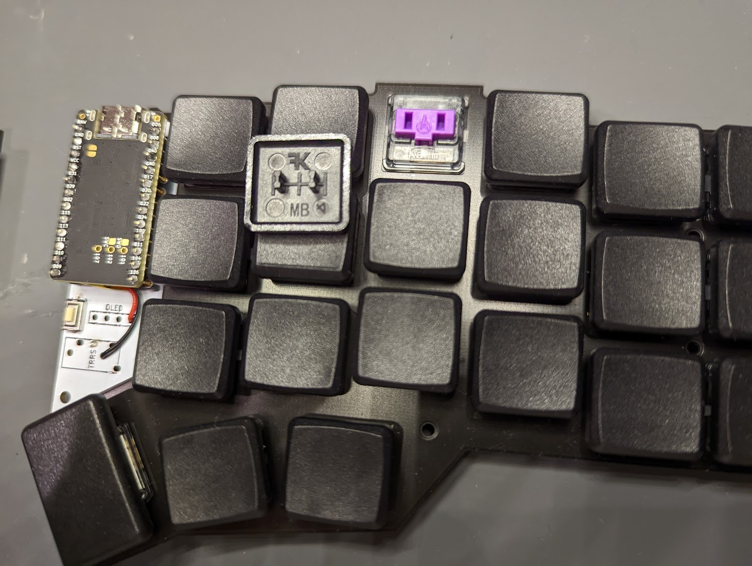
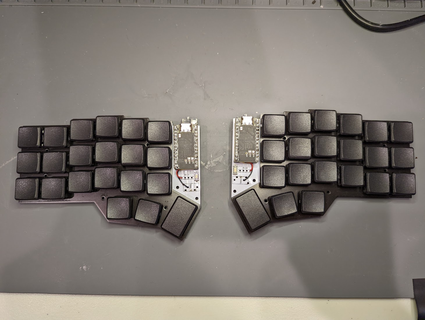
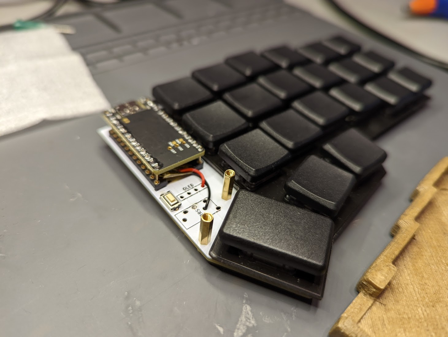
Place the batteries, and then the nice!nano µCs on top. The 301230r batteries (110mAh) are the perfect length-width dimensions for slipping underneath Pro Micro-sized microcontrollers. The batteries will add a little height, however, which is why we’re placing them underneath the microcontroller before, soldering the microcontrollers in place. Make sure the wires of the battery are facing the south side of the PCB, like in the photo below. Once you’re happy with the fit, solder on the microcontrollers.
-
Slip the battery wires through some unused PCB holes. For the wireless build, we’re not using the OLED screens, because we want to conserve on battery. We’re also not going to use the TRRS, because this build is wireless. So I just slipped my wires through some of the holes meant for the OLED and the TRRS, as shown below. When slipping the wires through these holes, no electrical contact should be made. We’re slipping the wires, just so we can access the bottom side of the PCB.
-
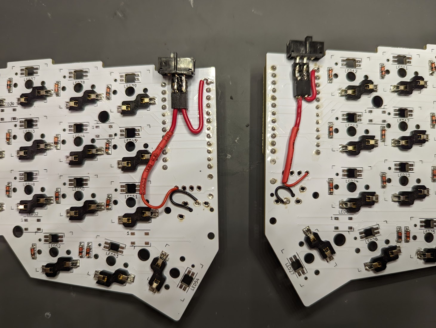
Solder the SPDT slide swithces. This part is a little trickier. In short, we want to install switches that can turn the battery power off, so we can conserve on battery when our keyboard is not in use. The GitHub link mentioned above is especially useful for this part (underneath the “Assembly” heading). We solder the black GND wire of the battery to the GND pin on the TRRS jack, which is shown in the below photo. We then solder the red VCC wire of the battery to the common (usually the middle) pin of the slide switch. We then solder an adjacent pin on the switch to the RAW pin on the microcontroller, which is also shown in the photo below. In short, we’re inserting a switch between the battery GND and the VCC (RAW). The slide switches I’m using are from Adafruit (805).
Case
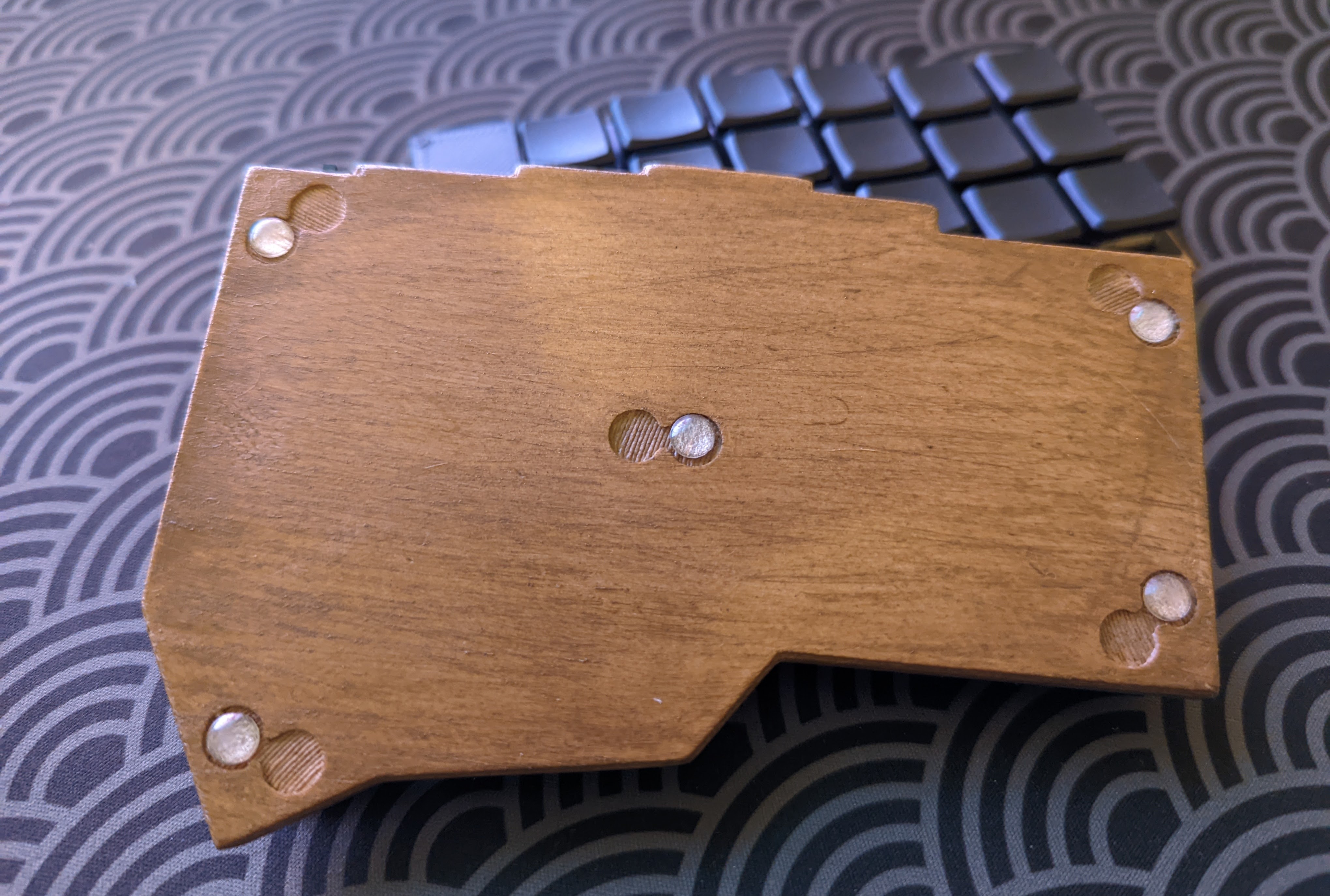
I wanted a case that was low-profile, with a somewhat portable feel. For that reason, I decided to remix this case. I modified this case by getting rid of the TRRS jack slots, and by adding a slot for the SPDT hardware power switch to the battery. My modified case can be downloaded here.
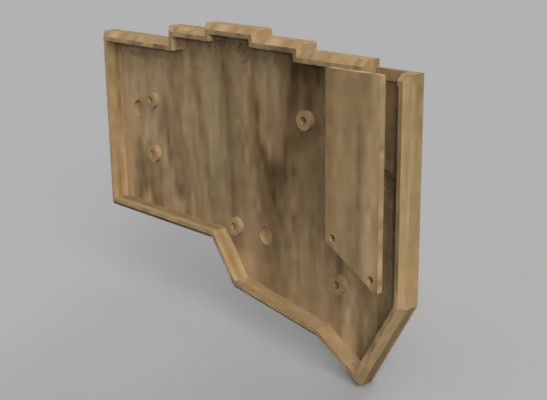
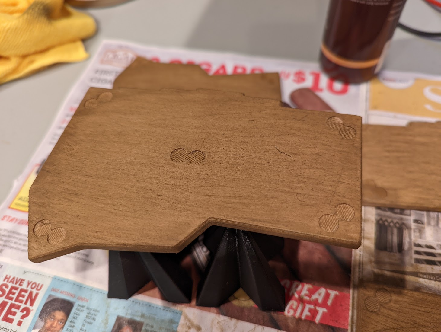
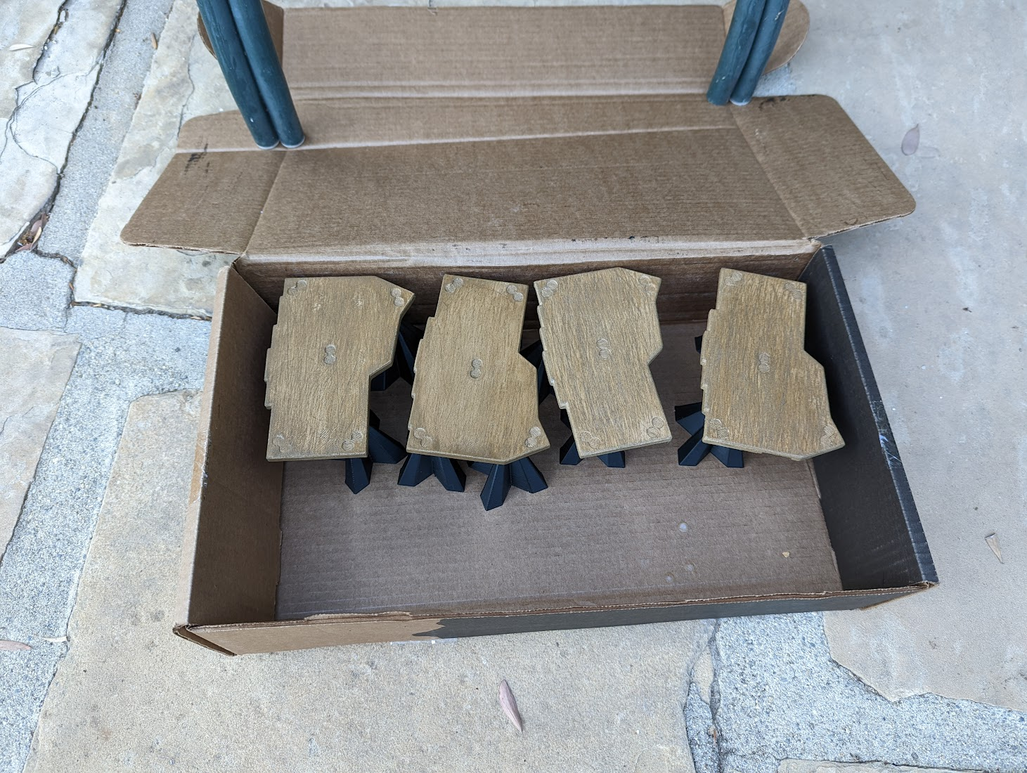
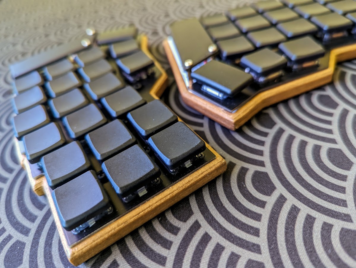
I printed the case in ColorFabb’s woodfill PLA. I then processed the case as described on Justine Haupt’s excellent blog post. In short, I used coarse 60 grit sandpaper to generate pseudo-‘grains’. I then stained the case with some cheap wood stain, and added some polyurethane coats for protection and aesthetics.
Finishing Touches
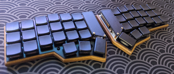
I added some choc purpz (25 g) switches, as well as some MBK low profile keycaps.
I use M2.5 x 6 mm screws to screw the PCB into the integrated standoffs of the case. I think M2.5 is a little coarser than the intended threads for the case, but I was too lazy to make threads properly, so I just used the screws to shoddily ‘self-tap’ threads into the wood PLA. This lazy ‘self-tapping’ works out, just because PLA (even composites) are quite soft. I also use M2 x 10 mm + 6 mm (x length of standoff + length of threads), brass, to hold up the top covers that hide the µCs.
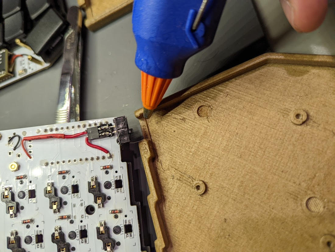
I also added a very small dab of hot glue to prevent the slide switches from getting pushed too far back into the case with repeated use.
Admire Your Work!
Tada! ![]() Admire your good work! Use ZMK to upload firmware, and you should be good to go!
Admire your good work! Use ZMK to upload firmware, and you should be good to go!
My ZMK-powered firmware is here.
Future Improvements
I think I’d make the following improvements, if I had to do this build again:
- I didn’t talk about the magnets I added inside this build. That’s because they didn’t really work out. Next time, I’d have to edit the casae so that the recesses for the magnets are larger–the polyurethane coat adds a bit of thickness, but I think the original source file’s recesses aren’t large enough–at least for my liking. I should also purchase stronger magnets, maybe some very legit ones from K & J Magnetics.
- I think I’d print the top cover with a textured bed, just so it matches the kind of ‘matte’ vibe of the rest of the case. I could also potentially change the design, so that the top cover ‘spills’ onto the sides as well a little bit.
- I’d use black instead of brass M2 screws to secure the top cover onto the keyboard. Again, for aesthetic purposes.