I’ve been doing more remote work these days, and so I figured I should invest in a decent webcam. I didn’t want to break the bank though, and I already own a Raspberry Pi Zero W1, a Pi HQ camera (which boasts an insane 12 MP), and compatible C- and CS-mount lenses. So I googled if I could somehow make the Pi and its corresponding HQ camera into a webcam. Turns out I can! I use the popular and open-source (![]() )
) showmewebcam software, which is super easy to install and use.
Software
One of the many interesting things you can do with the Pi is that rather than use it as a single board computer that hosts USB devices, you can make the Pi itself become a USB device. In Linux land, the conversion of a Pi into a USB device is referred to as “gadget mode”, and we are going to use a fork of the uvc-gadget driver to do so. Well … we’re not going to work with the fork directly, because showmewebcam does everything for us! The instructions page is pretty thorough. In short, all we need to do is go to the repo’s Releases page, and download the latest image release for the Raspberry Pi we’re using. I’m using a Pi Zero W, and as of today, the latest release is v1.91, so I download this image. We then use an iamger like the Raspberry Pi Imager or Balena Etcher (I tend to use the latter, but it truly doesn’t matter), and select the image we just downloaded. We then flash that image onto a SD card and we pop that SD card into our Pi. That’s it! The software side is all done.
Hardware
There’s not much to the hardware either. For a bare bones set-up, all you need to do is connect the Raspberry Pi to the Pi camera2, plug a micro-USB cable to the USB port closest to the centre of the Pi, and call it a day!
We’re going to be slightly fancier though, and use a 3D-printed case. Aesthetically, I really like the case I chose, but there are some design errors. I corrected them on the fly, in the laziest way possible, and I document those corrections (some of which are subpar) below.
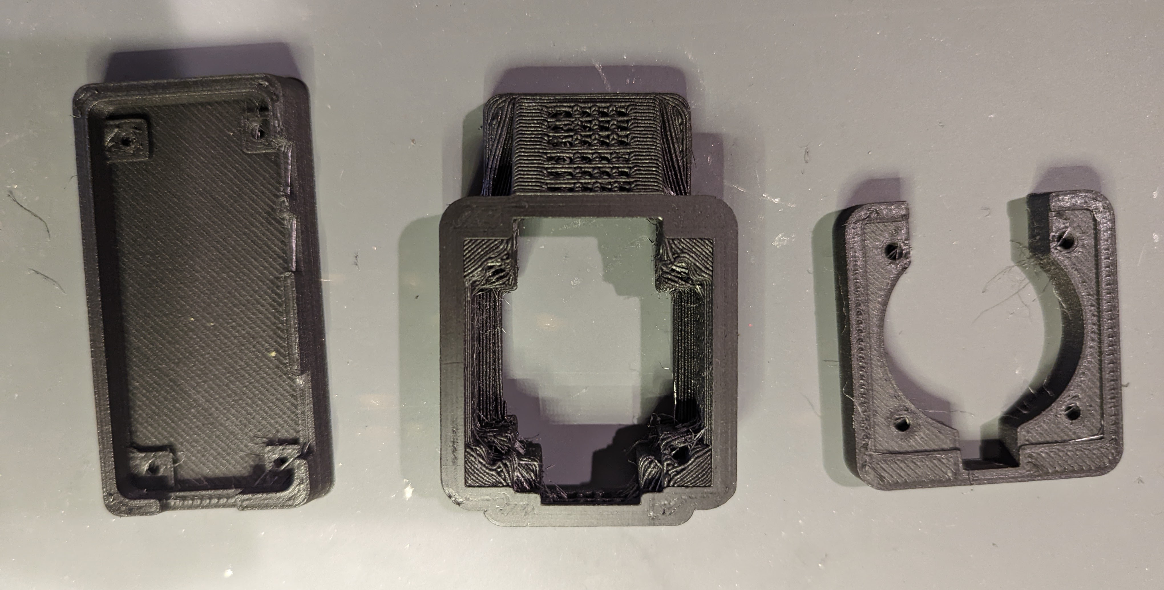
I printed all the parts in Matte Fiber HTPLA in Black and start assembling the base.
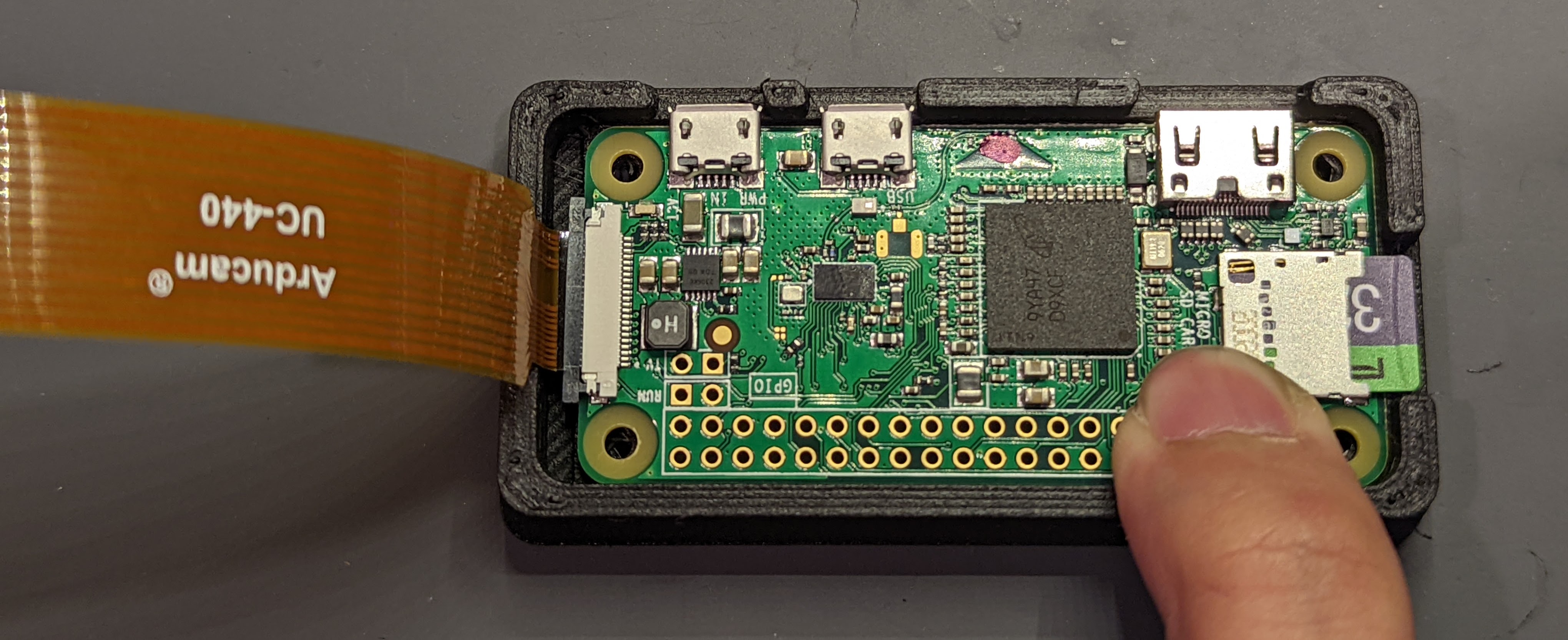
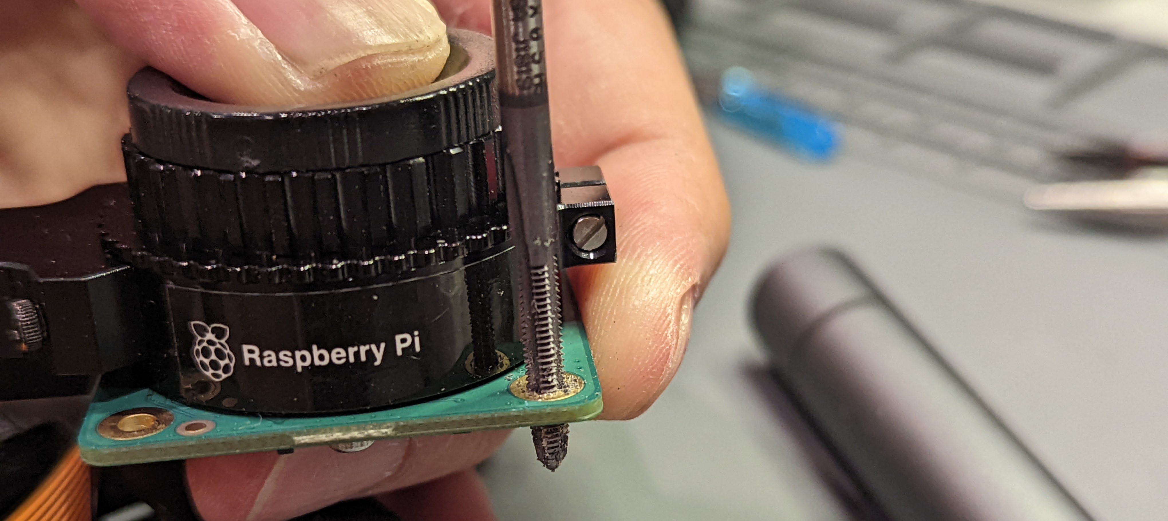
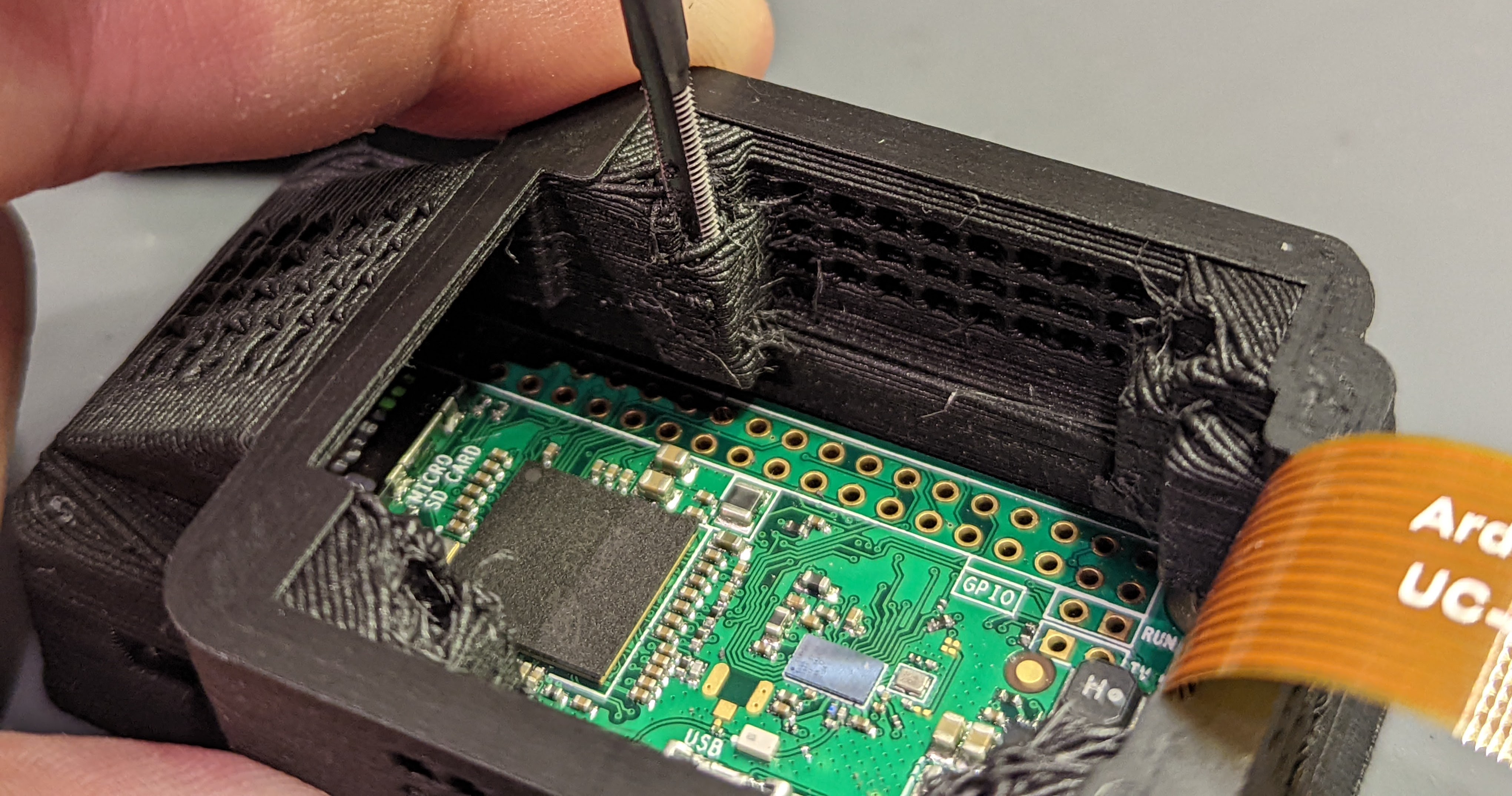
The design file instructions suggest M3 x 10 mm screws for securing the Pi into the base, but I found the M3 threading to be a little too large. The M3 screws wouldn’t really fit into either the case’s base, or the Pi Zero’s mounting holes. If I was being proper, I’d modify the case to accommodate for M2.5 screws (or possible M2 screws), but I was feeling lazy. The ideal on-the-fly modification would be to use a drill bit to widen the Pi Zero’s mounting holes such that they become M3 clearance holes, but I was too scared that I’d damage the Pi3. Instead, I carefully used an M3 tap to tap threads into the Pi’s mounting holes4. I also used the M3 tap to tap threads into the middle part of the case5. I then secured the case base, the Pi, and the case middle together, using the M3 x 10 mm screws.
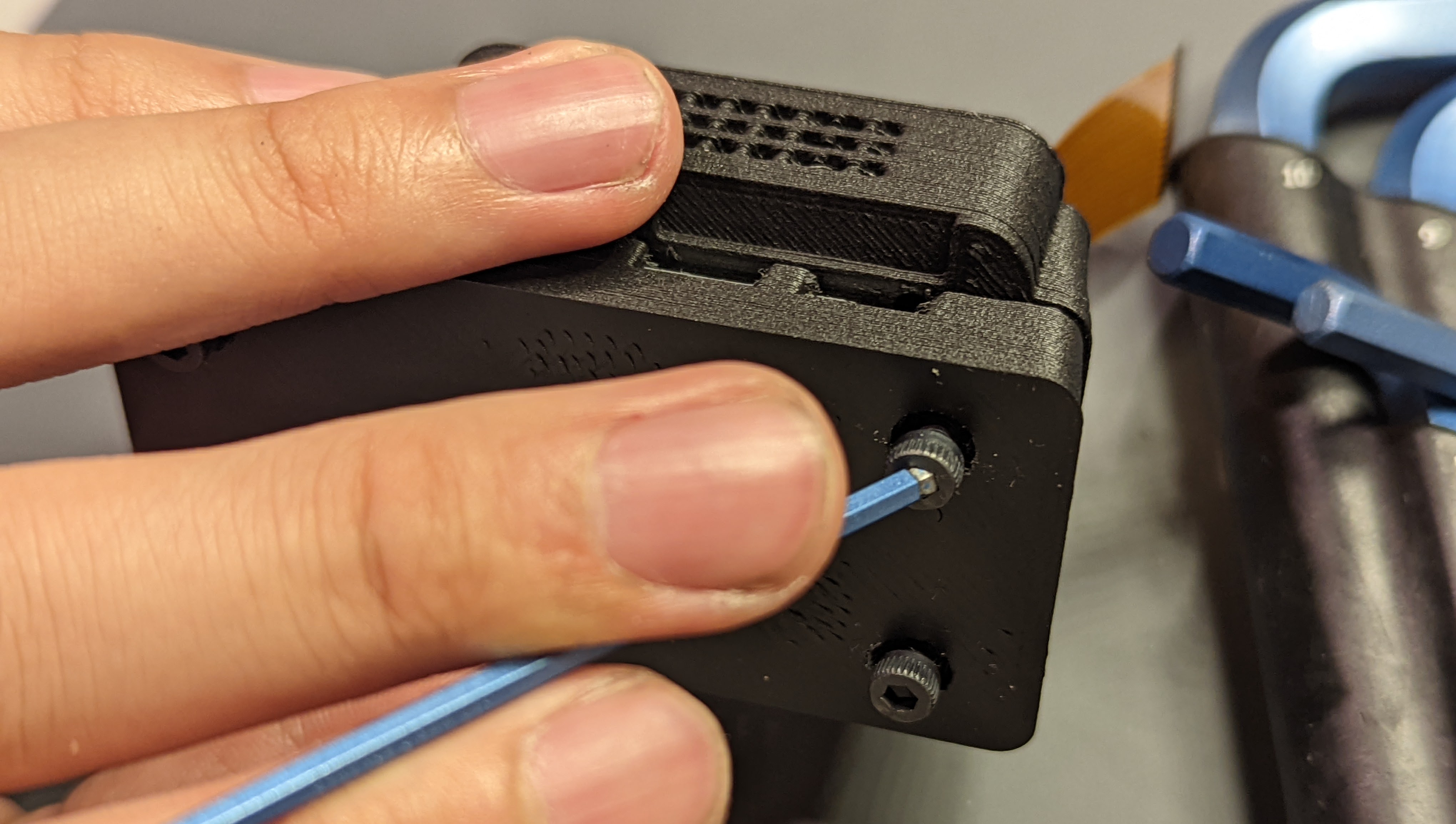
The Pi HQ camera is secured to the case, in an identical fashion to the Pi Zero, but upside-down and with a suggested screw size of M3 x 20 mm. Again, however, the holes of the case are too small for M3 threads, and this time, the recommended screw length of 20 mm is actually too long. I used M3 x 16 mm screws, instead. This time, I used a drill like I’m supposed to, to turn the holes closest to the screw head—those on the case’s top layer—into clearance holes.
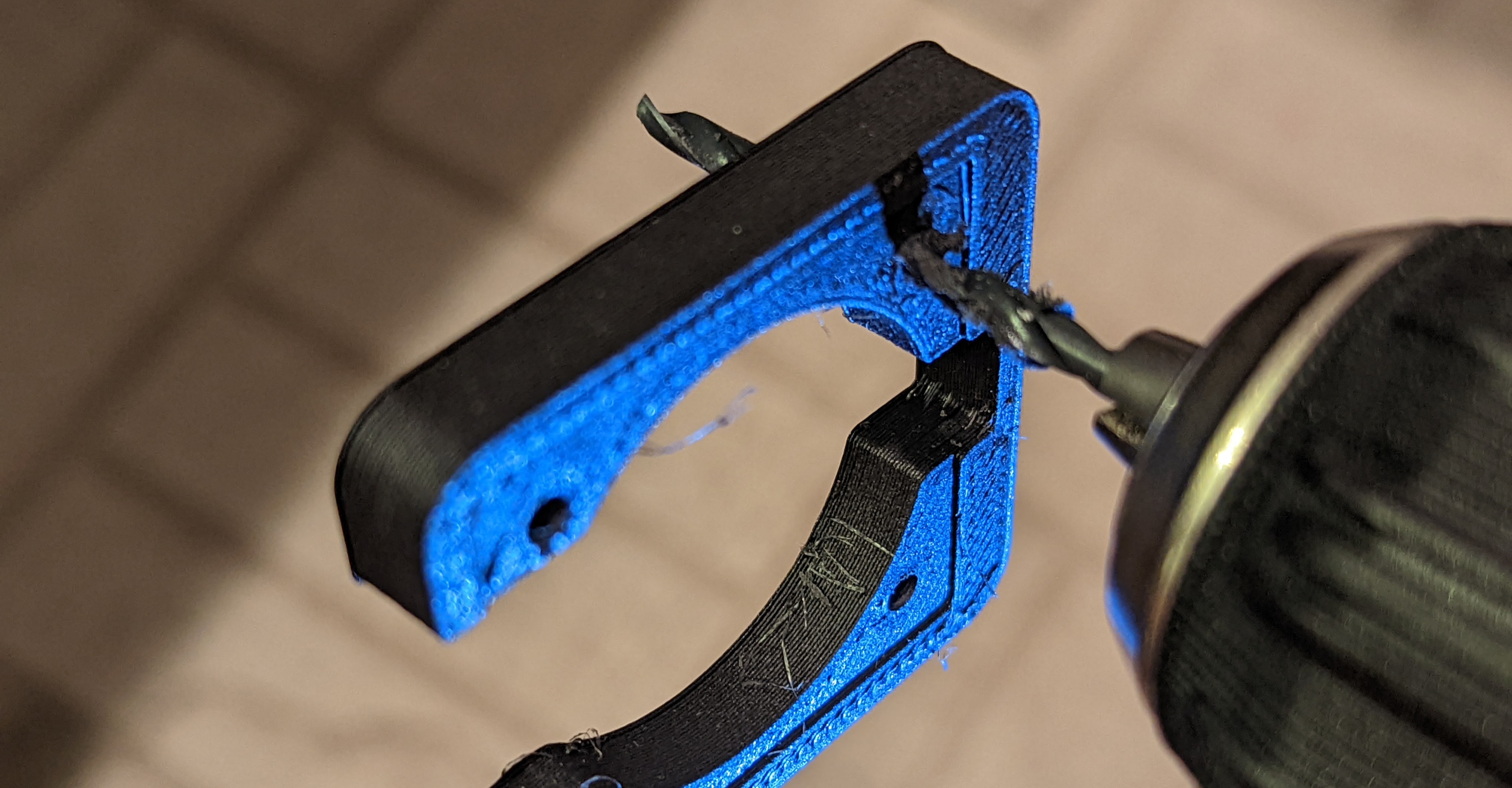
I should have done the same with the Pi camera’s mounting holes, but I was scared that I’d crack the camera’s PCB. So like with the Pi, I tapped threads, even though doing so is definitely not the ideal practice here, and I should have made M3 clearance holes instead :shrug:.
I tap the holes that are on the top of the middle part of the case, because those holes secure the Pi camera and the case’s top layer to the rest of the case6.
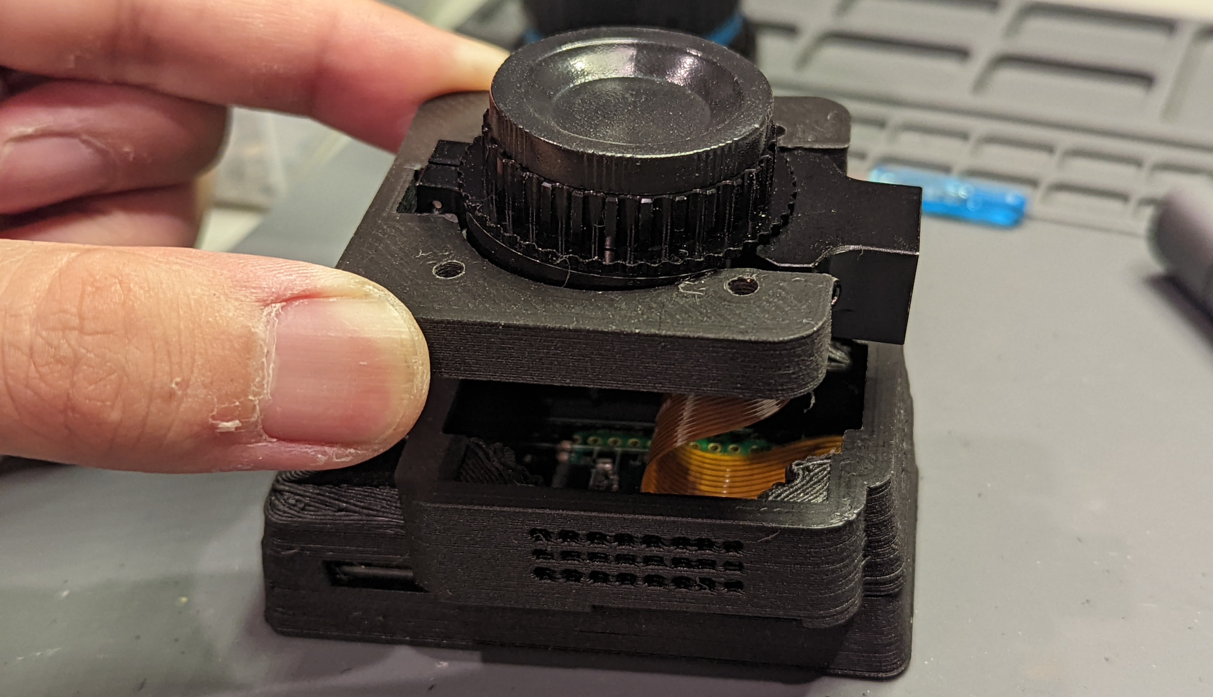
I then secured everything together with the M3 x 16 mm screws!
I used the C / CS threads to mount a 16 mm telephoto lens to the camera.
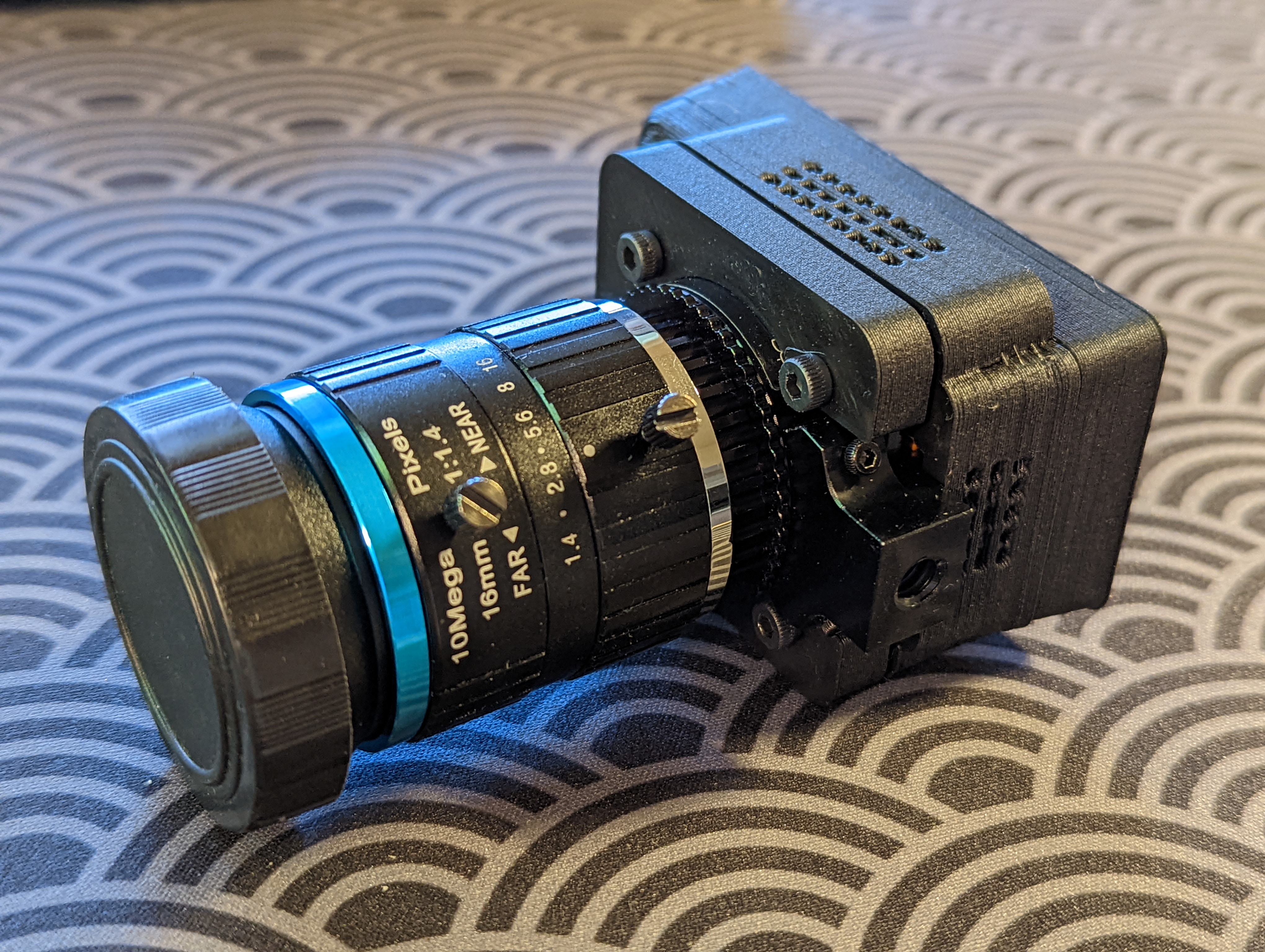
I plugged the camera into my Windows PC, and voila! I didn’t need to install any software, the computer knew exactly what to do ![]() ! Start up time after plugging in the webcam was about 5 seconds, which was faster than I expected!
! Start up time after plugging in the webcam was about 5 seconds, which was faster than I expected!
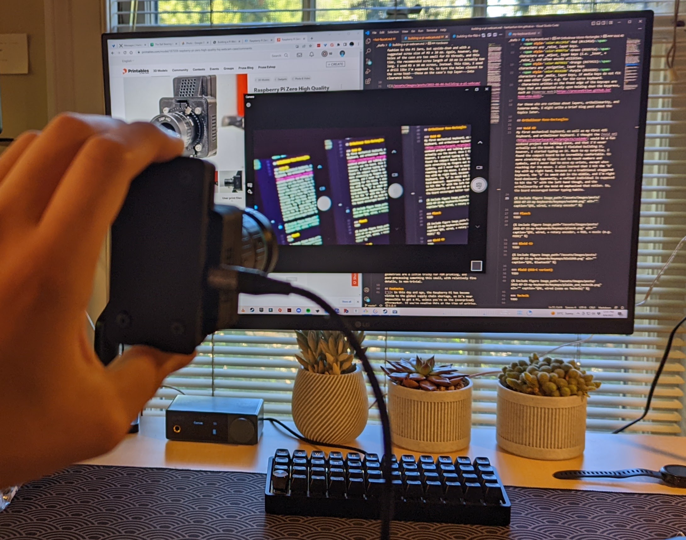
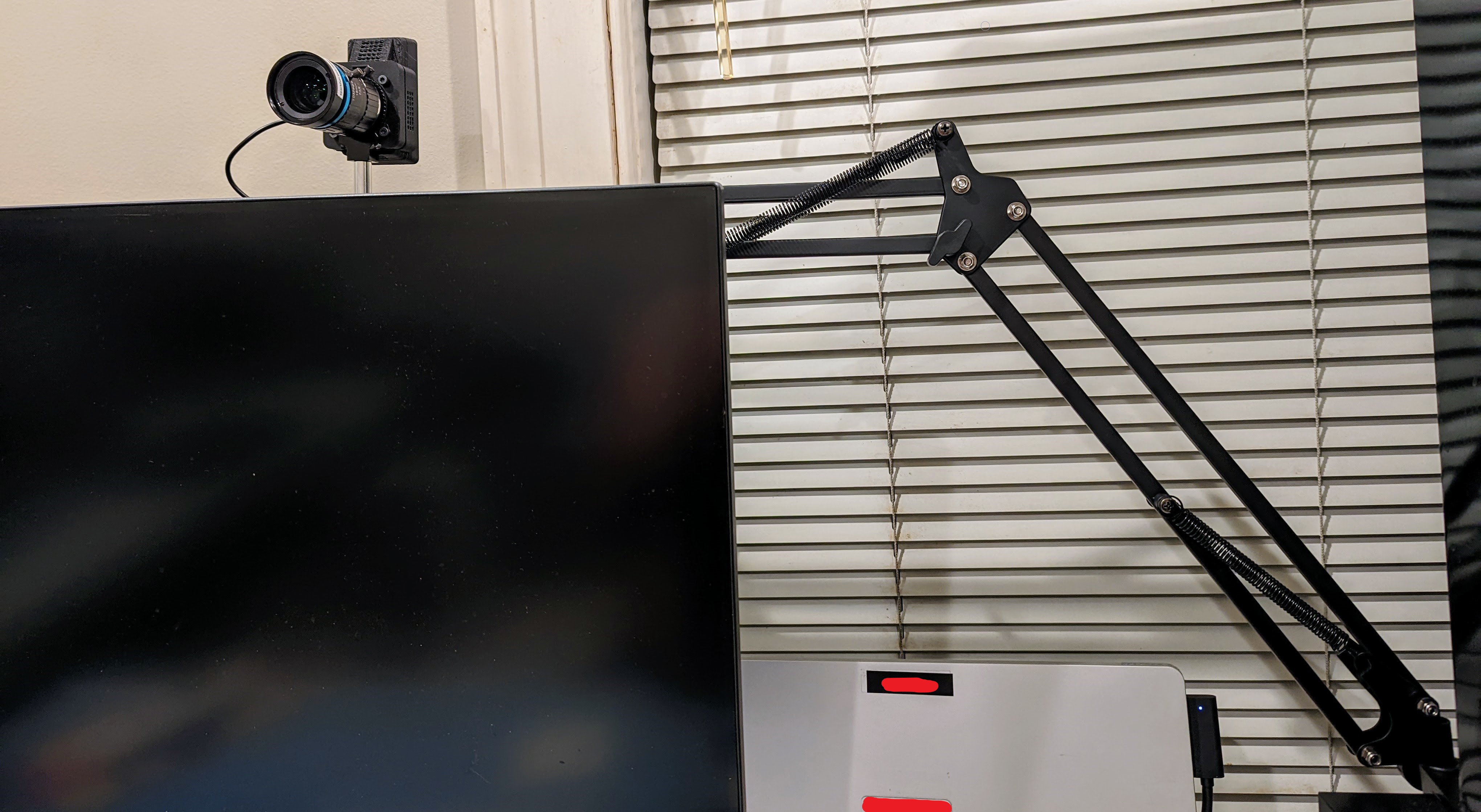
I tried doing the same on my Ubuntu machine, but it resulted in some issues. Apparently, the newest Ubuntu (22.04) appears to have some issues with the showmewebcam code, but hopefully that’ll be patched some point soon. As part of my final set-up, I mounted the camera via its 1/4”-20 threads onto a microphone arm stand.
Future Improvements
- I would most certainly improve the terrible hole-sizing of an otherwise cool and compact case.
- I think I’d also get this case printed in nylon from a place like PCBWay. Some of the geometries are a little tricky for FDM printing, and post-processing something this small, with relatively fine details, is non-trivial.
Footnotes
-
In this day and age, the Raspberry Pi has become victim to the global supply chain shortage, so it’s near impossible to get a Pi, unless you’re on the (overpriced) aftermarket. If you’re reading this at the time of writing, this project might not be as cheap as it should be.
 ↩
↩ -
If you’re connecting a Pi Zero (W or not) to a Pi camera, a special CSI cable is needed, because the form factor on the Zero is smaller than other Pis. ↩
-
The current supply chain issues mean that I can’t just replace the otherwise cheap and readily available Pi. ↩
-
If I was being self-respecting and correct, I would not be tapping thread here, because one should never have consecutive taps across two materials. Adjacent taps will almost certainly not line up in such a way that the tapped materials will lie flush with each other, and will result in an uneven mount. Yolo, oh well, they’re just PLA-printed parts
 . ↩
. ↩ -
Ideally, all the holes would be clearance, except for the layer furthest from the screw head, which would be tapped. In this case, I should have widened out the holes with a drill on the case base and the Pi Zero’s mounting holes so they become M3 clearance holes, and the holes on the middle part of the case should be M3 tapped, which is the one thing I did properly here. ‘ ↩
-
To emphasize, tapping this part with threads is correct and ideal. ↩


