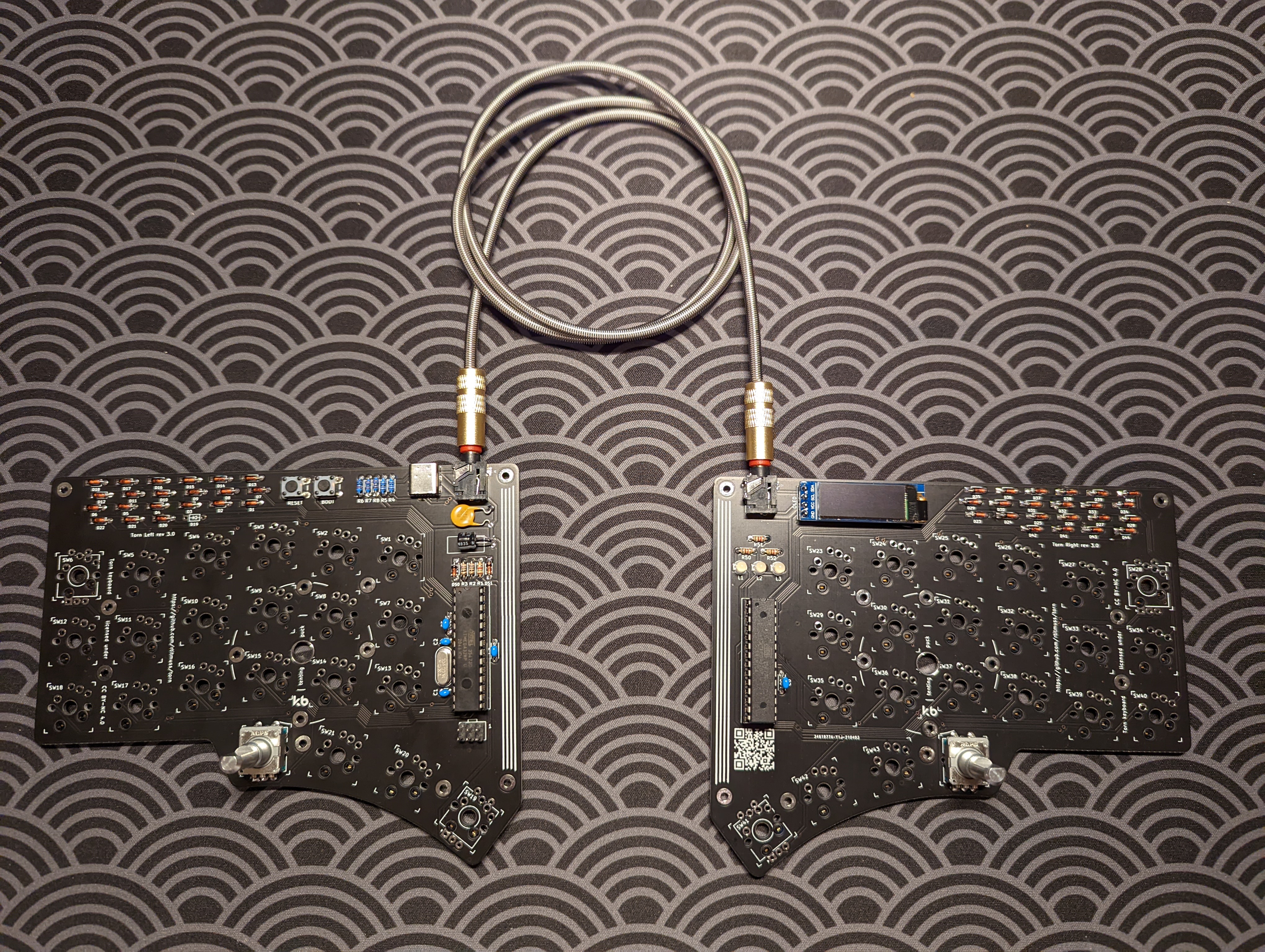
In this post, I build the Torn keyboard! Like all my keyboards, it’s a 40%, and it’s also a wired split. It also sports some fun features that my other keyboards don’t have. Namely, it has two rotary encoders, as well as an OLED screen.
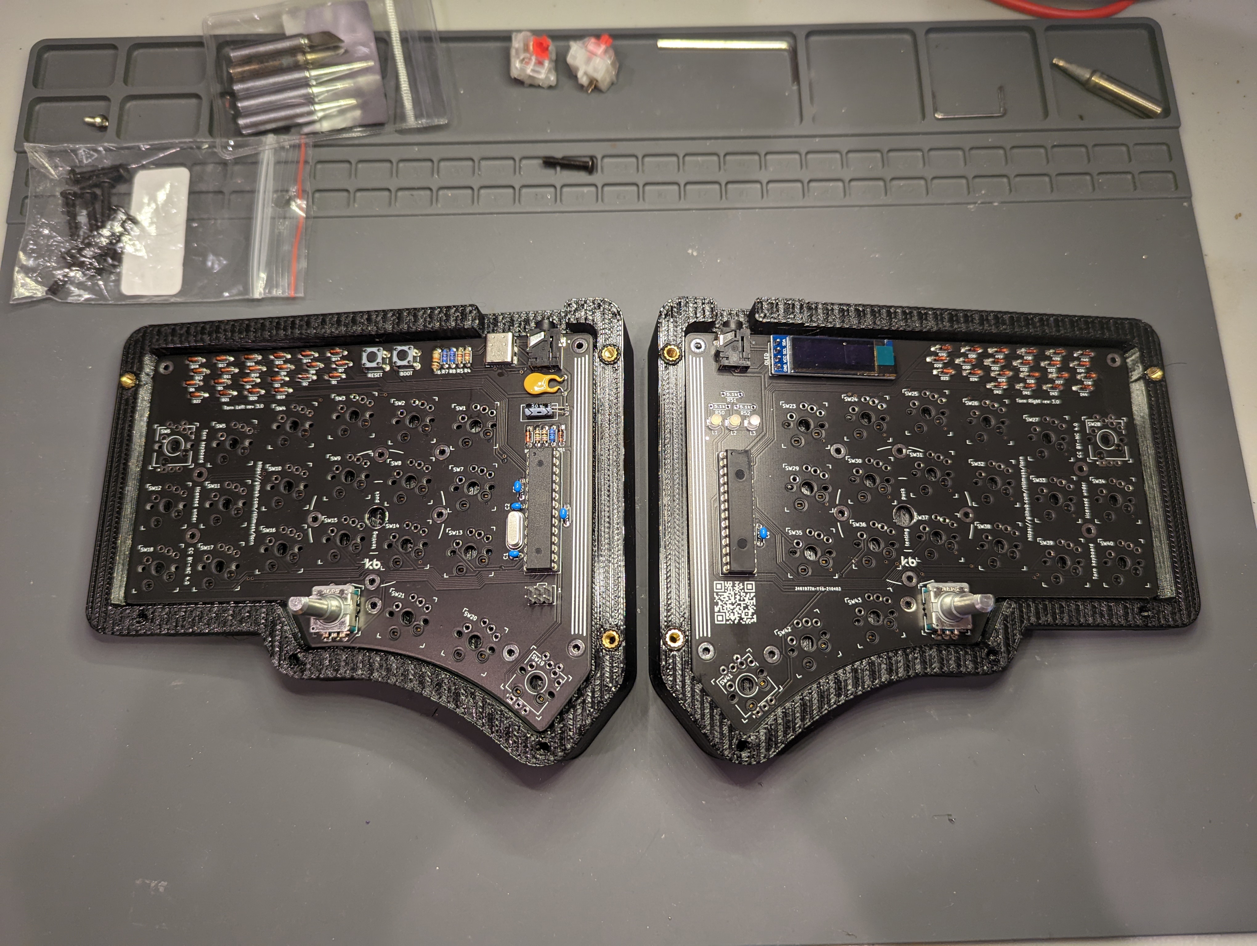
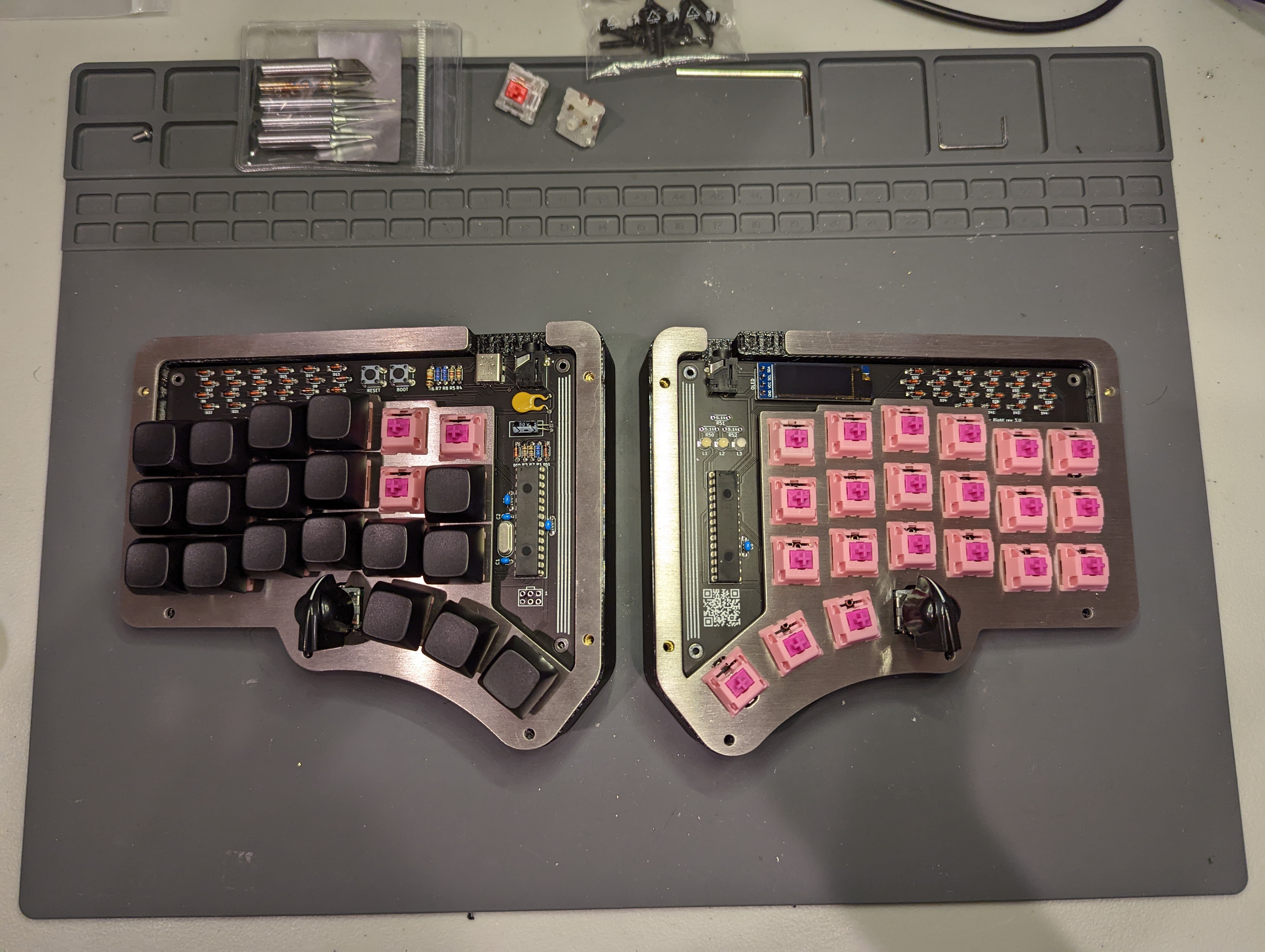
The Torn’s PCBs are not reversible. In some ways, I kind of like that. You can more easily cram a bunch of features in, such as supporting different switch and socket types.
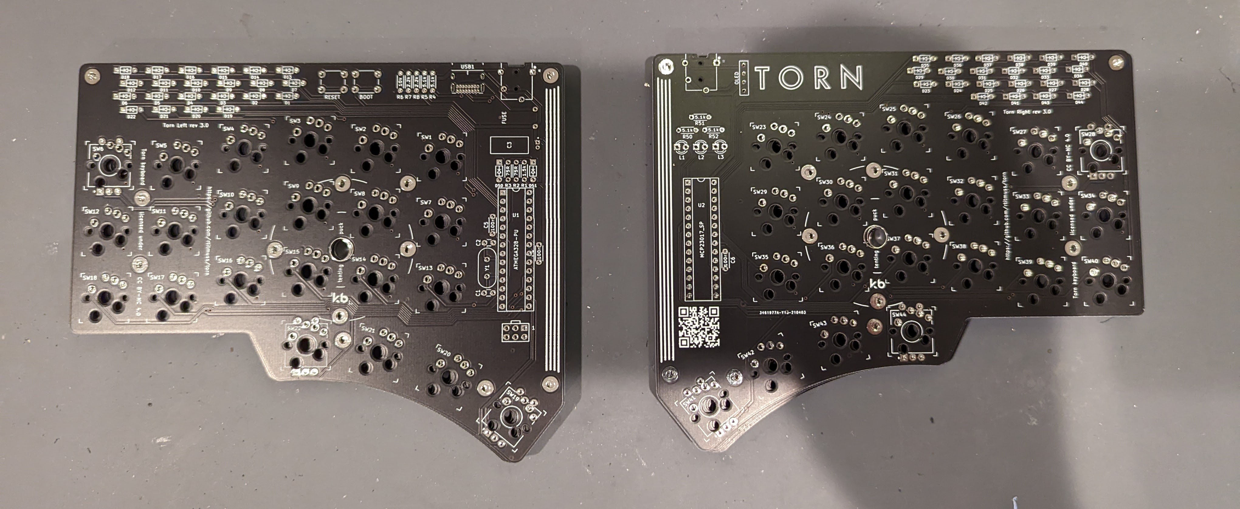
The keyboard uses some fairly standard keyboard electronics parts. In general, the documentation for the Torn is insanely good. I just followed the PCB assembly guide, exactly. The result is a fine looking keyboard.
The designer of the Torn also made a few case options. One of the really intriguing designs was the tented ‘wedge’ case. This design is not open-sourced, however, and I needed to ask the designer, Richard Titmuss, for the files. I messaged him on Discord (I found him via the very helpful Torn Discord server), and for a very modest price, he shared with me a .stl of a 7 degree tented version of the wedge case (for the price, he also shipped to me a pair of steel switch plates and acrylic covers). I printed the case in black PETG.
The case has two printed components that layer onto each other: the “trim”, which sits on top, and the “base”, which sits on the bottom. I started by preparing the trim. I used a soldering iron to install some M3 threaded brass inserts into the three lower holes of the trim pieces (even though, in the end, I opted not to screw anything into these threads).
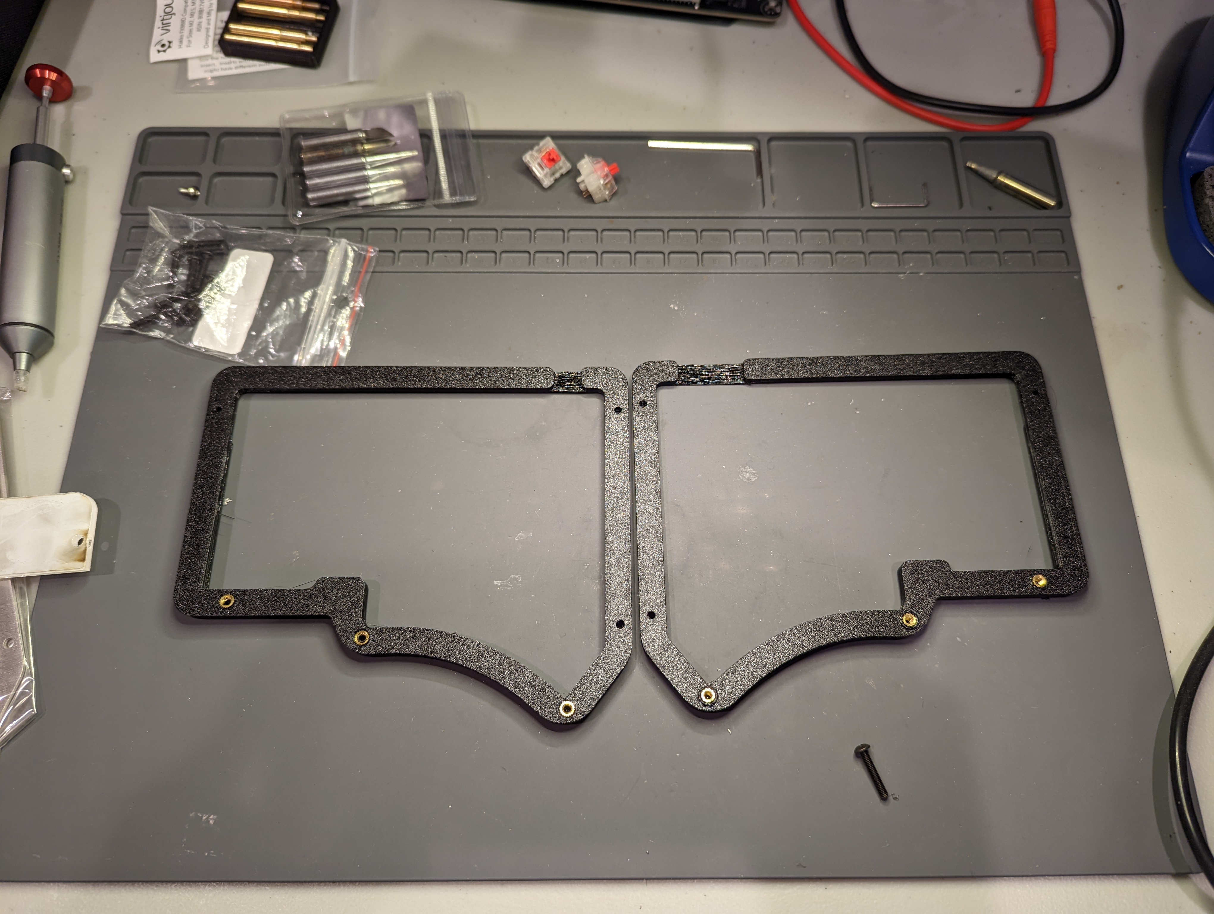
I then installed three M3 threaded brass insets into the three top upper holes of the base pieces. I placed the PCBs onto the base.
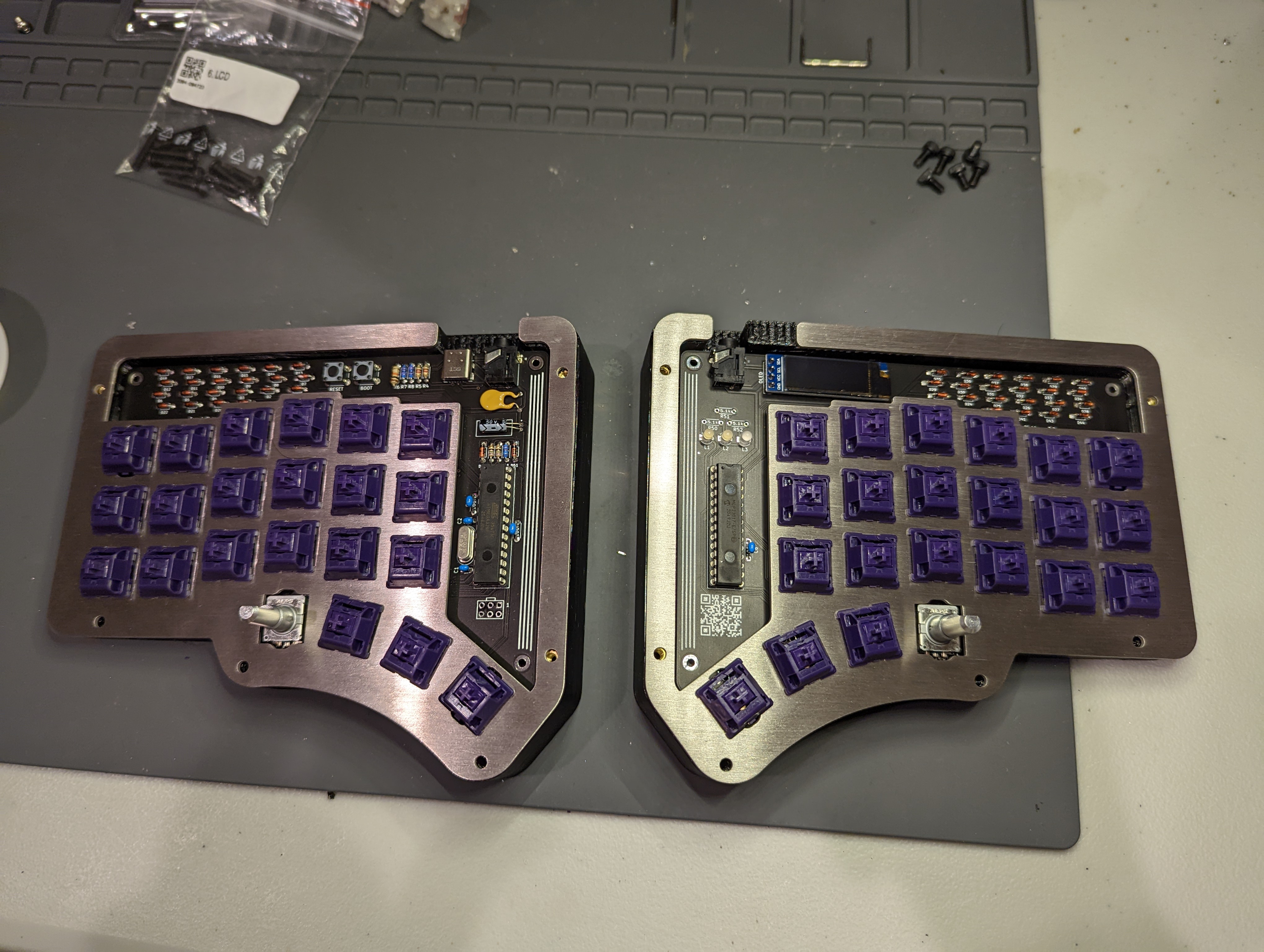
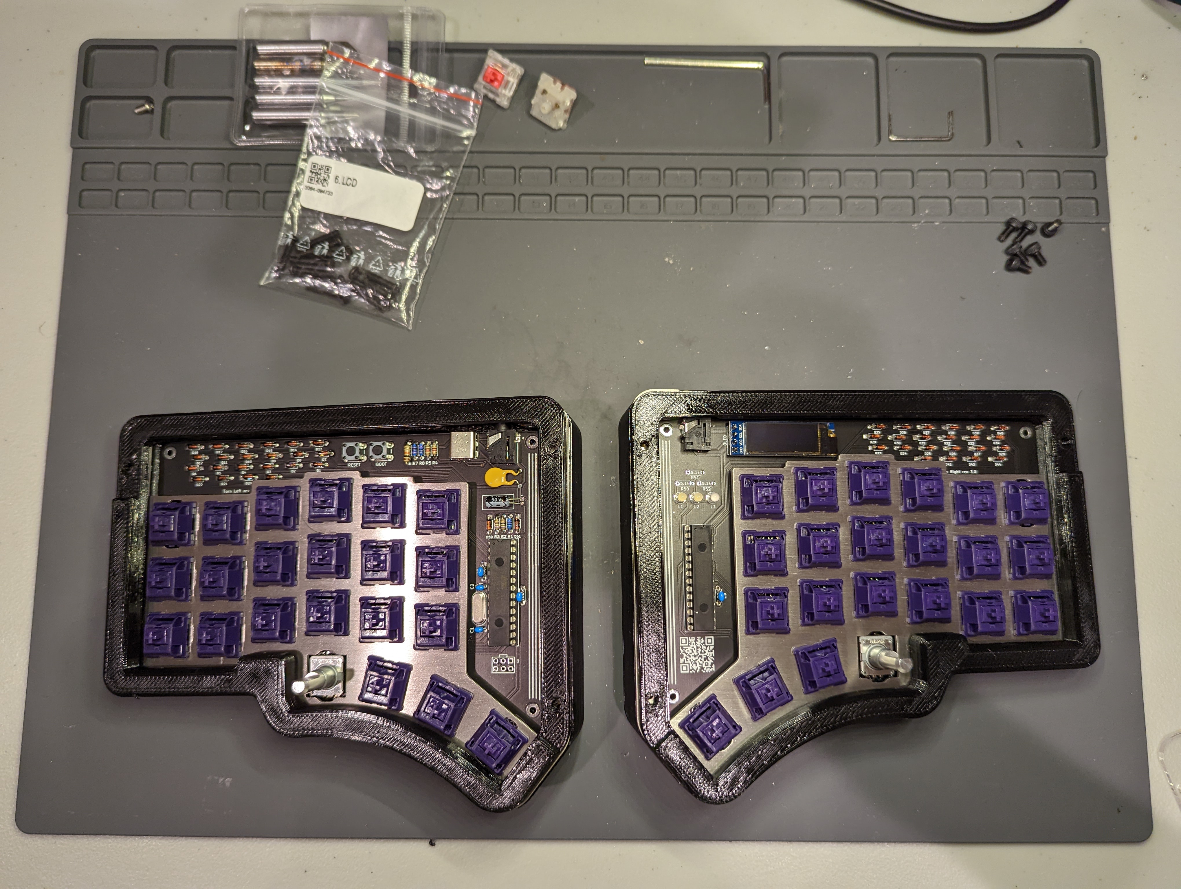
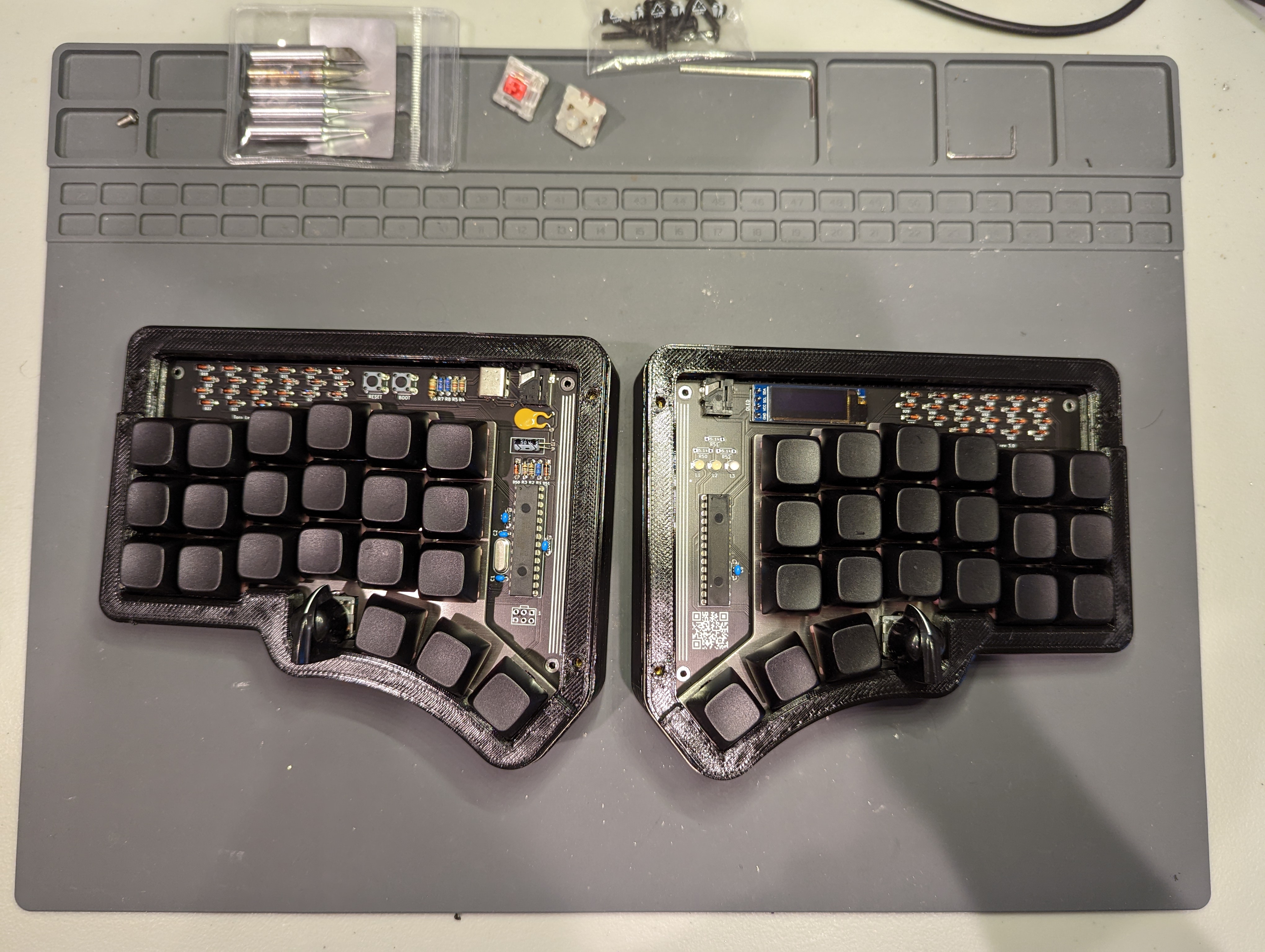
I then installed my switches into the switchplate and PCB. My PCBs have Kailh hotswap sockets, so my switches had to be press-fit into place. For this step, I found it easiest to remove the PCBs from the case, so that I would avoid bending the switchplate as I pressed the switches into the PCBs.
At this point, I uploaded the bootloader. For detailed instructions, see my blog post about uploading keyboard bootloaders.
I then placed the trim on top of the switchplate. Before moving on, however, I had a change of heart and opted for silent Boba Gum switches (68 g), because I want to use this keyboard at work without being super disturbing. I threw on some black NPT blank keycaps.
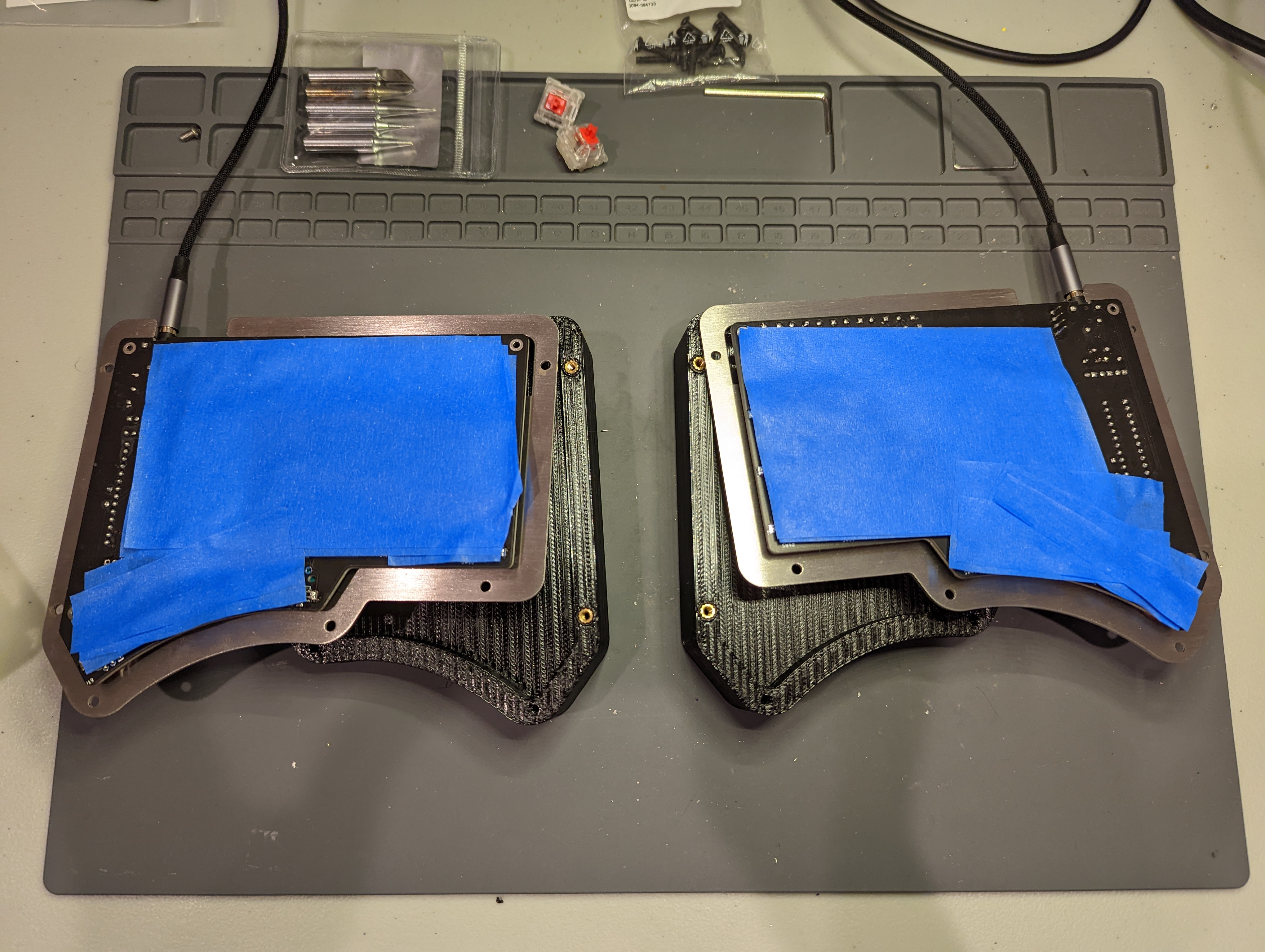
I wasn’t very concerned with the keyboard’s sound profile, because I was using silent switches. Still, I decided to do the tape mod, and I put on three layers of 3M blue tape on the underside of the PCBs. I also added a thin layer of drawer liner inside the base of the case.
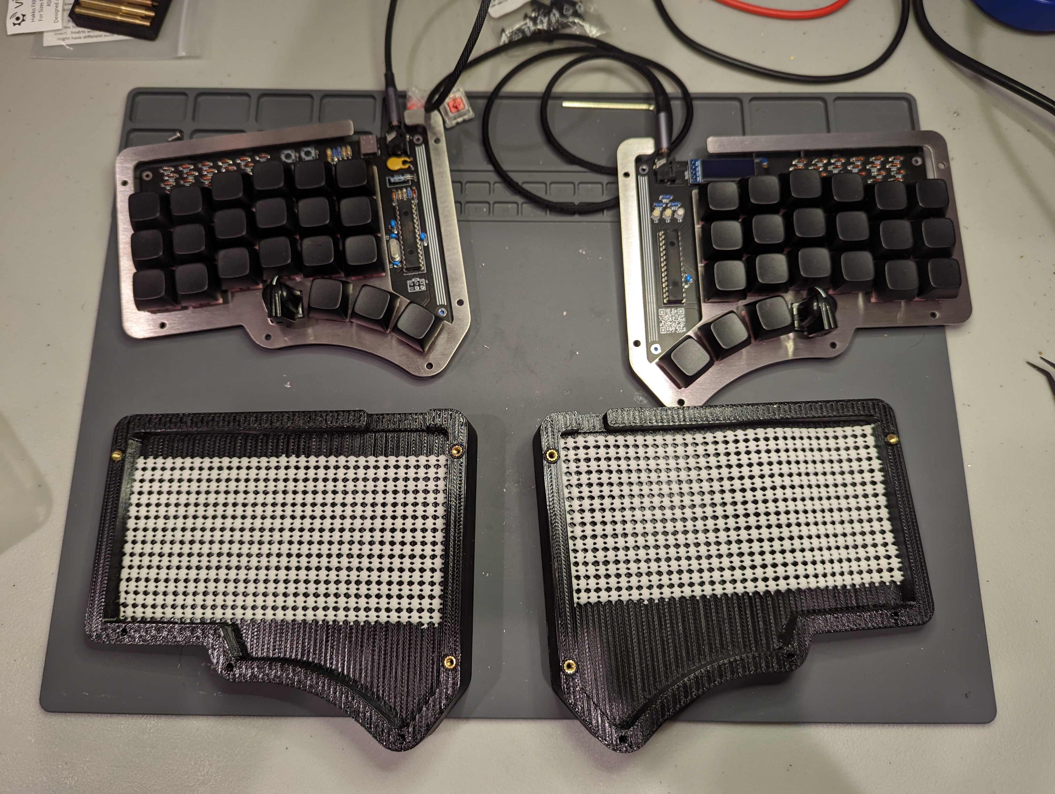
Finally, I added the acrylic cover and secured all the pieces together with some M3 x 10 mm screws. My rotary encoders spring back into a home position, so I also installed some aggressively tabbed “chicken head” encoder knobs. I think the final result is quite nice!
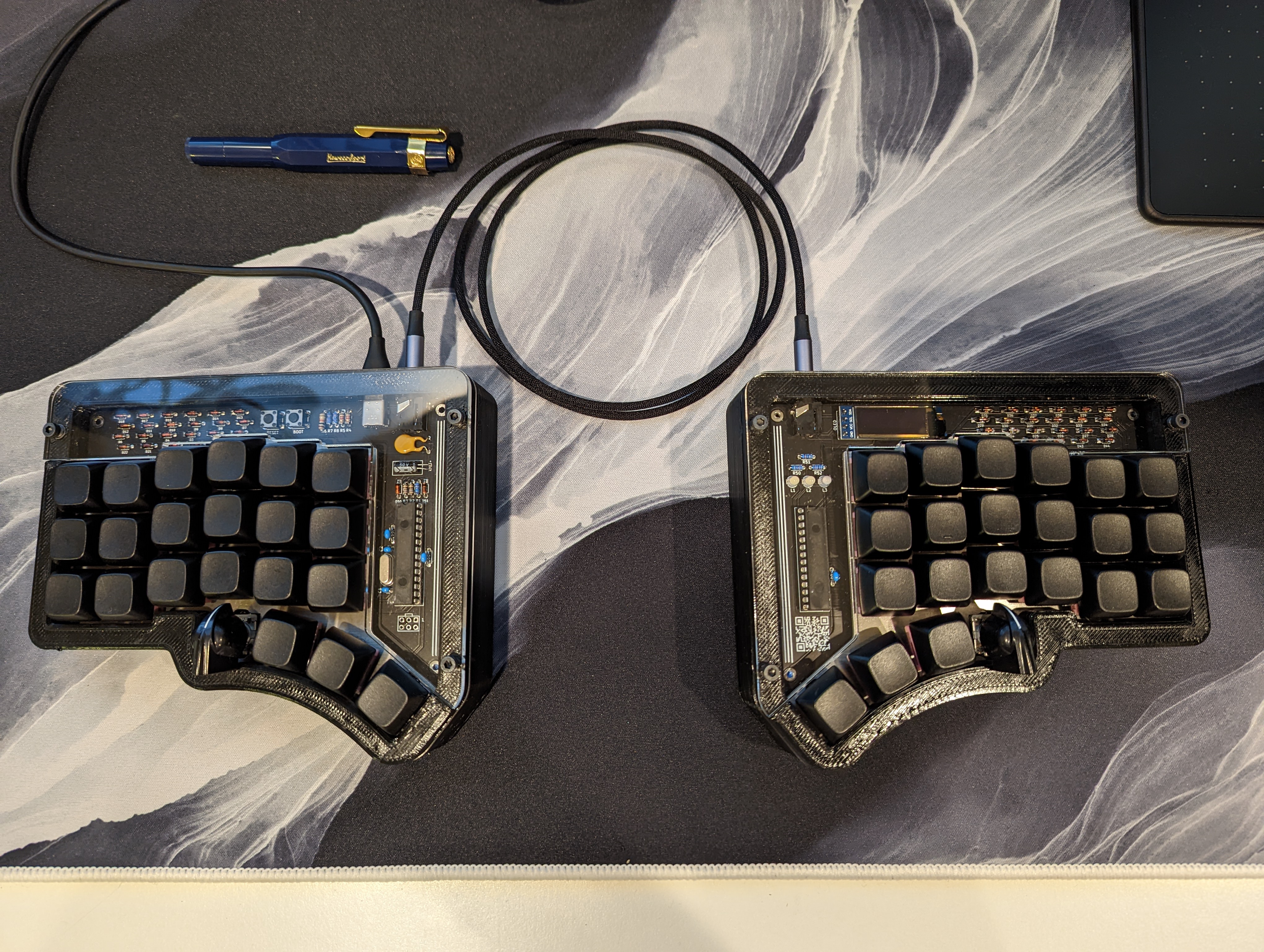
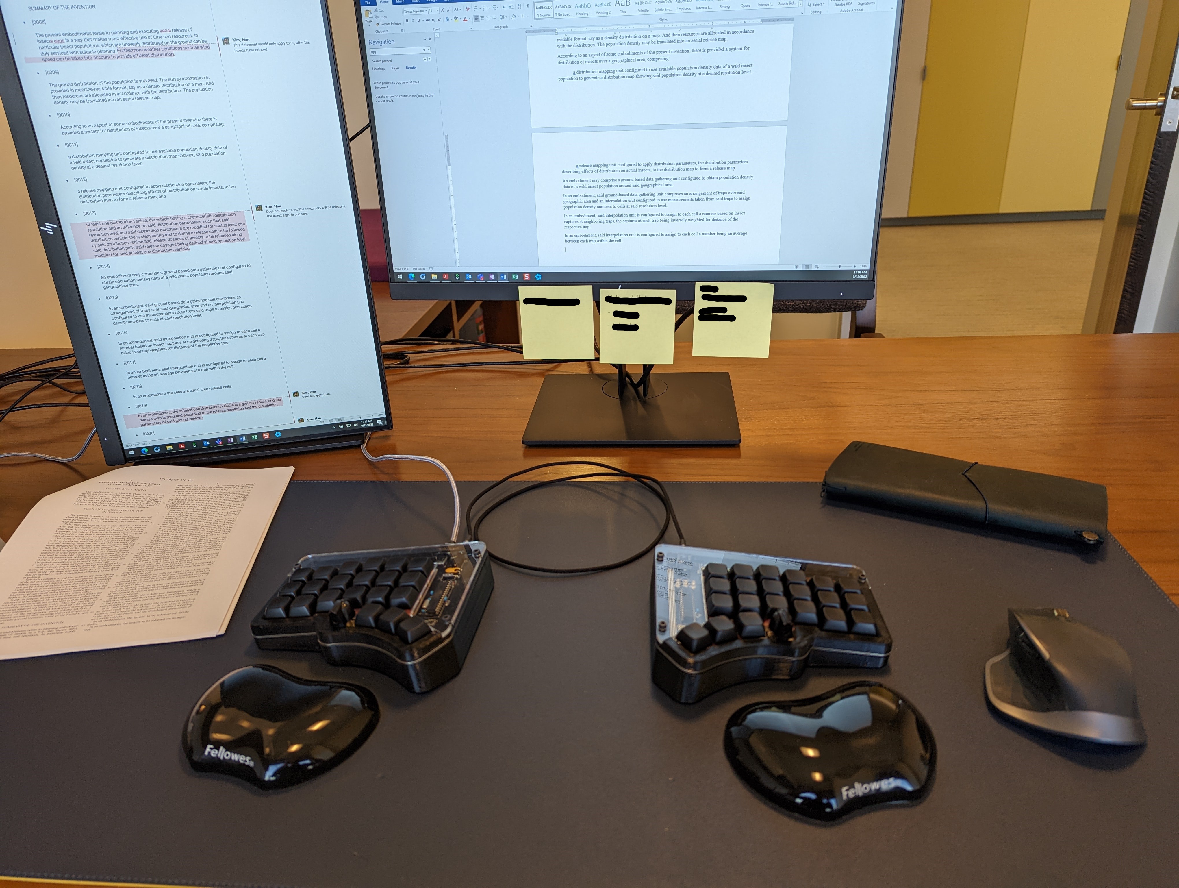
I brought the keyboard into the office, and I paired the board with some Fellowes wrist rests, to complete the office ergonomics look. The keyboard is both super comfortable and super silent ![]() .
.